The Duo-Disk Antenna
The Duo Disk Antenna, an experimental project at antenneX, is even more compact than the CFA, perhaps more powerful, and seems to have more versatility, although much is yet to be discovered about the DDA. Further, it was found to tune up more quickly and quite happy operating from within the house on top of a card table. The size for the 40-meter version is obvious as it set beside a coffee cup in the picture above. For those truly looking for a little antenna for the attic or closet, this may be just what you’ve been looking for! It displays another amazing phenomenon in that it operates with little or no fading! Using an A/B test with an inverted V antenna (located about 100 feet, or 30m away), the little DDA outperformed.
Further comparisons to the compact ground plane CFA, the DDA design departs with some important differences in the physical makeup of the antenna and makes it somewhat easier to construct and use. There is a major alteration of radiation polarization, switching from the original vertical polarization to horizontal polarization due to the alteration of the physical design of the antenna. The ground plane has also been eliminated. It just isn’t needed!

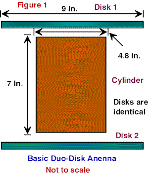
In Figure 1, the basic antenna can be seen as a spool shape, thus the DDA. The disk on the top of the cylinder changes the entire RF characteristics of the antenna from that of the CFA. This is seen by the polarization of the radiated field changing from vertical to horizontal polarization.
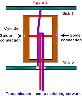
Figure 2 shows the method of feedline connection to the elements of this antenna. The feed for the cylinder comes up through a hole in the bottom disk and then is soldered to a crossbar that passes from one side of the cylinder to the other. This crossbar is soldered to the sides of the cylinder in the center of the cylinder as measured from one end to the other. Good insulation from the disk feedline is required.

The feed for the two disks is accomplished in the following manner. The top disk has a hole drilled in the center of the disk and the bottom also has a hole drilled close to the center of the disk. A wire is pushed through the bottom hole and soldered in place. This wire has to be long enough to pass through the cylinder and up to the top disk. The feedline for the two disks pass up from a hole drilled in the bottom disk and then goes upward to the top disk. After all internal connections are soldered; the wire going to the top disk is passed through the top disk and soldered to the top disk and the disk tied down to its supporting
Dimensions
The following dimensions will give you some workable dimensions and will allow you to build an antenna that will work at first try. BUT, this are not necessarily the most optimum dimensions. We at antenneX and the GARDS are experimenting with other measurements to see the effect on the frequency range. For now, if interested in experimenting with the DDA, try these dimensions. After you get a working model, THEN make changes to see if you can improve your signal strength over our original design.
78/F = Diameter of cylinder
1.25(diameter of cylinder) =length of cylinder.
2(diameter of cylinder) = diameter of disks
.25(Diameter of disk) = Spacing between cylinder and disk
The particular DDA antenna I have been working with is approximately 7 inches (17.78 cm) high and has a diameter of 4.8 inches (12.19 cm), with a disk diameter of 9 inches (22.86 cm). This corresponds to a frequency slightly above 16 MHz. However it did work on 40 meters very well with all things considered, such as operating from inside my house and at a height of approximately 5 feet above ground. This particular antenna was not built by using these precise formulas, but rather with the materials on hand for expediency.
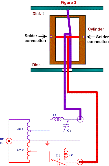
Now, Figure 3 shows our hookup to the Matching Network:

Construction
As far as construction is concerned, the cylinder was constructed from a section of brass tubing that was part of a steam line from a large ship. I happened to have this in my packrat box and had a friend cut it to length with a power saw. Other conducting materials can be used and there are sources of thin copper sheet available at hobby shops that can be used to cover non-conducting cylinders, such as lengths of PVC pipe. The large cardboard forms called Sonotubes here in the U.S used for forming the large cylindrical concrete pillars used for supporting structures in buildings and freeway overpasses will do quite well. They come in a variety of diameters and are easy to cut to length with a handsaw.
The disks were made from thin plastic covered with copper sheet. The copper was glued to the plastic with a small hole drilled in the center of the top plastic sheet for the feedline to poke through for soldering. The bottom sheet has two larger holes drilled through it where the feedlines for the cylinder and the two disks to come through. I used two 1/2-inch diameter (1.27cm) lengths of plastic tubing to insulate the two feedlines from each other. This particular version of the DDA I am experimenting with has a disk spacing of 1/16 inch (.16 cm) and even though it worked very well, I am not at all convinced this is the optimum.
Others have built the original antenna using aluminum foil wrapped around cardboard oatmeal boxes or other food type containers, with aluminum foil glued to cardboard for the disk and ground plane. Of course, these disposable antennas were not meant to be left outside and were cheaply built to see if the antenna would actually work. The builders of these simple antennas were rewarded with contacts over 8,000 Km on 40 meters.
As far as this antenna is concerned, the bandwidth was from 7.150 to 7.265 MHz, with center frequency of 7.210 MHz. This was at a 1.5:1 VSWR bandwidth points. This is far better than my inverted V used in A/B tests. By retuning the antenna, I could cover the entire band as well as a considerable amount above and below the band. Note: You cannot use a grid dip meter to determine the resonant frequency since this is not a resonant antenna.
On the Air Reports
All of my testing has been conducted primarily during the day and in A/B testing against my Inverted V with a height of 45 feet. The DDA did as well as a dipole at the same height. At a range of 20 miles, the reports were equal in strength, at 20/S9. Farther out at 40 miles, the V was 15/9 and the DDA was at 10/9. There was one report from about 200 miles out that gave the V 15/9 and the DDA 10/9. From there on out, to as far as I was able to communicate during the test period, the V was stronger than the DDA, but it was a lot higher both at the center and both ends by many feet. The greatest range so far was 500 miles (800 Km) and the V was S9 and the little DDA was between S7-S9. At all ranges beyond 90 miles, with the one exception, the signal reports were between S7-S9 consistently for the smaller antenna. One thing that stood out was the consistent lack of QSB with the smaller antenna. I thought this was rather strange, as even on the SW broadcast stations the signal levels were more consistent with much less fading than on the inverted V.
The antenna was tested for a week, then other things came into the line of fire and this antenna was set aside for more testing with a better matching network, which is now in progress. The new results will be published here as they come available. You can rest assured that this particular version will be improved on and there will be a great deal more testing of different configurations. In particular, the 160-meter and 80 meter versions will be next on the agenda for construction and testing.
I am sure that the LOFER experimenters will be interested in a version for 160-190 kHz, as this would be a nice little antenna for the frequencies of interest. That is a whole other area for experimenting. If you decide to try the DDA, please let us know what you find out. Also stay tuned in here at antenneX for help. The new Compact Antenna Forum is a good place to check in from time to time. I know the CFA Forum was of great help in those experiments. It’s a free service provided by this magazine and an excellent place to learn about new ideas and developments
Originally posted on the AntennaX Online Magazine by Richard Morrow, K5CNF
Last Updated : 16th May 2024
