CFA Construction Guide for 75/80 Meters
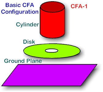
The basic configuration is shown in Figure 1 and can be seen to consist of three main parts: A cylinder, a single disk and a ground plane. Each will be taken up separately in order to deal with how that particular part can be easily built from what you may have on hand.
Building the Cylinder
First, build the cylinder. In Figure 2, the dimensions of the cylinder can be seen. The height of the cylinder is 25 cm or 9.84 inches. Now, what you decide to use to make the cylinder will depend on what is available to you. If you only have things like cardboard tubes or other non-conducting material, you must first cover the material with varnish or something similar. Fiberglass could also be used to cover the material. No matter what is used, you must protect it from the effects of moisture and weather. PVC pipe of a suitable size is another alternative. As far as metallic pipe is concerned, Aluminum, copper, brass or bronze would be good. Any other metal would be extremely lossy and cause the antenna to perform badly.
Again, if a large cardboard tube, such as carpets are shipped in, or other similar non-conductive materials, you must cover it with some sort of conductor after it has been coated with shellac or varnish. Thin sheet brass, such as found in craft or hobby shops will work fine, and it can be glued in place or fastened with double-sided tape. Since the diameter of the cylinder is so large it will no doubt take several sheets of brass to cover the entire cylinder. This will require soldering the sheets together. No, you cannot use copper window screen. It will corrode and not be a very good conductor. The conductor must be of one single cylinder made of a conductor or cylinder wrapped with a conducting sheet.
Assuming the cylinder has been covered with a suitable conductor, connect a wire across one end of the cylinder to the other side so it bisects the opening. Make a good solder joint at both sides and then paint or lacquer coat the cylinder to protect it from the weather. The wire just installed will be the connection to the matching/phasing network, which will be completed later.
Build the Disk
The disk shown in Figure 3 may be made of solid aluminum such as a large pizza plate or other large sheet of aluminum. It also could be made of plywood or heavy cardboard that has been waterproofed by heavy coats of shellac or varnish. Coating with fiberglass, or a very thin plastic sheet, is also acceptable. Here again you must use some sort of conductor like thin brass or copper sheets to form the conducting and transmitting surface of the disk. As with the cylinder, the disk must be weatherproofed. The center hole of the disk must be of the dimension shown. Now, connect a wire from one side of the hole to the other in order to distribute the current equally across the disk. This will be the connection for the matching and phasing network.
Ground Plane Construction
The ground plane (Figure 4) is the easiest part of all to build and can be made of mesh or sheet aluminum. It may also be made of plywood or other similar material after it is suitably covered with varnish, shellac, or polyurethane finish. But, again you must use a conducting material such as sheet brass or copper for the actual ground plane. A connection must be made to the ground plane by the matching/phasing network and should be close to the center of the ground plane as possible. This connection, as with all the others should be protected from the weather by some coating of some sort of shellac like polyurethane varnish, fiberglass, or similar coatings.
Illustration Figure 5 is what the finished CFA looks like without the tuning network, which should be located under the ground plane.
Figure 6 shows several examples for making the supporting insulators for the disk and cylinder. Wood covered with several coats of shellac or polyurethane or fiberglass may be used as well. Pieces of PVC or acrylic plastic is another option. Glass insulators could be used, if located of the correct length
Figure 7 is the finished CFA with the matching/tuning unit mounted under the ground plane.
Editor’s Note: If you plan to build one of theses CFAs, It is not recommended to use the phasing/matching network described below in this article unless you are a highly-skilled Engineer. Rather, the reader should consider using an alternative one described in subsequent articles.
Figure 8 is the diagram of the matching/phasing network. Build this exactly as shown or the CFA is not likely to work. It is strongly suggested that you do not use coax lines for phasing or matching. Such “delay lines” do work bit are difficult to work with.
Now that you have some ideas of how you can build a CFA, it is time to go build one. By the way, if you don’t have any T130-2 toroids handy, send an e-mail request to info@antennex.com at antenneX and we’ll provide you with one or more supplier source.
Originally posted on the AntennaX Online Magazine by Richard Morrow, K5CNF
How to Build a 75/80 Meter CFA
Editor’s Note: There is a great deal of vital information about building a CFA in this article, but do not use the phasing/matching network as described. A flaw was found in the phasing/matching network described in this article, and has been revised in two additional construction articles in the next issue for February 1999. If you plan to build a CFA, the T130-2 or T200-2 Toroids needed can be found in the Shopping Shack on this web site.
After the preceding series of articles on the theory of Crossed-Field-Antennas (CFA), I am sure most of you will think this is the most important article in the CFA series. It presents the details on how to build and tune a CFA for 75/80 Meters. Actually, this is a two-part article. antenneX editor, Richard Morrow, K5CNF has taken the details and devised methods to simplify construction of this CFA. That article is entitled CFA Construction Guide for 75/80 Meters and will be found in this same issue of antenneX. As supporting documentation, readers are encouraged to obtain a copy of US Patent # 5,155,495 which may be found at the IBM Patent Server <www.patents.ibm.com>.
Mr. Hately and Dr. Stewart selected the 75/80-Meter ground plane version of the CFA as one of the least complicated for construction by Hams. This same physical unit works well on 160 and 40 Meters as well as 75/80 meters, but requires significant changes in the phasing/matching network. In addition, the toroids create problems on 160 meters due to being lossy at the lower frequencies. All of you who are interested in experimenting will find this CFA easy to build, tune and achieve high performance. With that experience behind you, some trial and error will allow you to achieve comparable performance on other bands. antenneX will be interested in heating about the reports from you on your experiences. The best phasing/matching network designs reported by eXperimenters for the other bands will be reported to allow sharing of that information.
Physical Dimensions
NOTE: The dimensions used by the developers are in metric units. To convert cm to inches, divide cm by 2.54. Approximate values are presented, exact values can be determined by the equation above. However, the approximate values shown are sufficiently accurate.

With reference to Figure 1, the following physical dimensions are presented:
Ground Plane: 1 meter square (approximately 40 inches on a side) made from mesh or sheet aluminum.
D Plate: 40 cm (15.8 inch) diameter aluminum, with a hole of about 6 cm (2 1/4 inches) diameter cut out in the center. Position the D plate 10 cm (4 inches) above the ground plane with a suitable insulating material.
E Plate: Cylinder height 25 cm (about 10 inches), Cylinder diameter 20 cm (about 8 inches). Position the E plate (cylinder) 10 cm (about 4 inches) above the D plate, using a suitable insulating material. Construct the E cylinder from aluminum, or if desired, aluminum mesh.
Phasing/Matching Network: The schematic diagram presented in Figure 2 details the phasing/matching network. The values presented on the schematic are those necessary for operation on the 75/80-Meter Ham band. Many Hams have reported that they have tried to build a CFA but were not successful. Unless the CFA is properly fed (as shown in the schematic), its performance will be poor or not at all.
Caution: The toroids and wire specified are for transmitter powers of 100 watts or less.
With reference to the schematic, the coax from the Transceiver may be any desired length. Best operation of this CFA will be achieved when it is located clear of all obstacles. Although the height is not critical, it may be necessary to mount it on the house roof or on a pole to achieve obstacle clearance. Tuning for the center of your desired operating frequency range should be accomplished with the desired length of coax. After tuning, the unit can be elevated to the desired height. Please be aware that this antenna has the same radiation pattern as a vertical wire antenna, thus it is not a good antenna for short-range communications (for distances less than about 500 ground miles or 800 km). The antenna can be mounted on its side and simulate a horizontal dipole. To operate in this manner, the height above ground will dictate the radiation pattern, the same as any horizontal antenna.
Transformer T1 provides impedance matching, thus, the number of turns of wire on the secondary is not the same as the primary. Since the secondary impedance is higher, thus the current is lower. The wire size on the secondary may be smaller than on the primary. There are two secondary windings. These should be slightly twisted prior to winding on the Toroid. Be very careful to observe that the two windings are out of phase with each other. This is very important to successful operation.
Both L1 and L2 consist of 22 turns of # 20 gauge wire wound on the same type Toroid as T1. Since there are three (3) toroids required, and they are a specific type of Toroid to achieve the desired inductance, antennex has made a special arrangement to make these toroids available to those who need the information. The ordering information is contained in the construction article.
Physical Considerations for the Phasing/Matching Network
Transformer T1 is best positioned underneath the ground plane, but it can be positioned in the D plate gap. The primary has 4 turns of # 16 wire. The secondary is wound with 20-gauge enameled wire, and consists of 2 windings each of 9 turns with opposite ends connected to the ground plane as shown in Figure 2. These wires can then be fed up from the ground plane towards the E and D plates. The inductances of the secondaries are not too critical for successful operation of the CFA but will be of the order of a few uH.
One end is the feed for the E plate, but before being connected to the E plate, it feeds a parallel resonant LC circuit (see Figure2) which is placed in series between the E plate feed and the final connecting wire to the E-plate. The parallel circuit comprises a variable 400 pF capacitor (e.g., ganged) and a 22 turn wound (again 20 gauge wire) T130-2 Toroid. The value of L should be about 5.54 uH. This tuned circuit should be secured inside the E plate cylinder using insulating material on which the tuned circuit can be mounted. A note of caution is that the capacitor should be accessible for adjustments by hand, about 30 or 40 cm (12 to 16 inches) away from the E plate. An extension made of either plastic tubing or a shaft with an insulated coupler may be used.
The other end of the feeder transformer feeds the D plate. However, it has an unusual arrangement, because the feed splits into two—see Figure 2. One branch feeds the D plate through a 22 turn winding (20 gauge wire) on a T130-2 Toroid placed in series. The inductance is again about 5.54 uH. The other branch is connected to one end of a variable 400 pF capacitor which is then connected directly to the ground plane. Again, this variable capacitor should be made accessible for adjustments, and should be secured somewhere close to the D plate.
Settings
For the CFA described above, on the 75/80 Meter band, appropriate settings for both capacitors should be about 330pF. The E plate capacitor is generally the more critical to set of the two capacitors.
Tuning
A field strength meter should be placed at a suitable distance from the CFA, and both capacitors should be “tweaked” accordingly until radiation is evident. As radiation occurs a drop in SWR towards 1:1 should be observed. The field strength meter need only be a very simple diode type with about 3 feet of wire as a suitable antenna. This will allow tuning using very low power, typically much less than one watt. You may desire to begin with a higher power, perhaps as much as 5 watts. As the tuning progresses, reduce the transmitter power as required to keep the field strength meter on scale. Be aware—the VSWR bridges in some transceivers will not indicate actual VSWR unless the transmitter power level is greater than a few watts. In that case, simply tune the CFA for best radiation as indicated by the field’s strength meter using low power. Following that procedure, increase the transmitter power to 10 watts or more and adjust the capacitors for lowest VSWR.
If the CFA is adjusted at some frequency, say 3.9 MHz, then the next step should be to measure the range of frequencies over which the VSWR remains less than the value at which the transmitter automatically reduces the transmitter power due to high VSWR. This will be the range over which the CFA will allow operation without readjustment.
This CFA will operate at other frequencies outside the 75/80-Meter band. It may require alteration of the windings, with different taps being required in order to achieve successful radiation at other frequencies. The keen amateur is encouraged to experiment.
Receiving
This antenna will perform well on both transmit and receive. Prior to the conception of the CFA, receive antennas were characterized by their “capture area.” Even though the CFA is extremely small, it does not have a corresponding small “capture area.”
All of us hope you enjoy using the CFA as much as we have enjoyed bringing these articles to you. For those of you who prefer to buy a CFA rather than build one, please stay tuned. Those details will be presented in the near future.
It has been stated that the CFA is a new concept and that various configurations are still being explored. We expect to present those variations to you as they mature.
We implore you to remember that the development of the CFA is protected by patents and any commercial gain from these antennas is solely for the benefit of the inventors.
From the days of Marconi until Mr. Hately and his cohorts came along with the CFA, there were only wire antennas. These people have done an incredible job in a short time to develop and deploy Crossed-Field Antennas. Because the CFA is new and is a radical departure from conventional wire antennas, many nay-sayers have pronounced the CFA to be less than it is. Now, any one who builds this version of the CFA will certainly become a believer. I am reminded of a quote from Dr. Stewart, “Antennas will never be the same.”
Originally posted using the same title on the AntennaX Online Magazine by Maurice Hately – GM3HAT, Dr. Brian Stewart – MM1DVD and Ted Hart – W5QJR
Last Updated : 3rd May 2024