No Adjustment 5/8 Wavelength 2-Meter J-Pole – Revision 1
There is nothing built that is perfect, and therefore nothing that can’t be improved. Yes, that includes my ‘stuff’. While the basic concepts and construction of the original version of this J-Pole design work well, there are some areas that can be improved. For details of the original version, please refer to my article in the October 2000 issue of antenneX (now in Archive IV).
The original version of this antenna was built with threaded aluminum rods for the radiator and the matching transformer, a Printed Circuit Board (PWB) feed that had a SO-239 mounted on it, and a wooden “F-frame” support. Experiences have shown that this was not always reliable in service, could be simplified and reduce the cost at the same time. I set out to identify the problems and to make it better. First problem: The fixed die used to form a thread on the aluminum rod cut a thread that was quite loose in the standard hardware store nuts I used. The nuts fit the tap snugly so I am forced to conclude that the die was undersized. The sloppy fit did not give enough mechanical strength and it was quite easy to strip the thread. The solution is to buy an adjustable die that can cut the proper diameter thread to correctly fit the nuts.
First solution’s problem: My first tap and die set had six-sided dies. The adjustable die is basically round, which won’t fit the handle I have. Therefore I cannot presently try to cut a thread of the proper size until I find a new die handle.
Second problem: PWB’s are difficult for the average radio amateur to fabricate. Associated with this is the additional problem of finding a solderable SO-239. I needed an alternative method of construction to solve this one.
For the “Rev. 1” antenna I used 1/32 x 1 inch brass plate I obtained at a local hobby store to replace the PWB. (click for metrics conversions) The conductor sizes are the same, but they now must be held to the wooden “F-frame” with short #6 brass screws. This is less precise but easier to fabricate. #6 brass screws are also used to mount the SO-239 instead of solder so now any SO-239 may be used. Other connectors or a coaxial cable pigtail could be used but I have not tried that yet.
Alternative Construction Details
Once again, It will be helpful to refer to the original article I did on this J-Pole. Looking for a more practical way for the average Amateur to construct this antenna, I decided to drill and tap new rods for #10 machine screws. (Whoa! Hold off drilling holes in your existing rods if you have already built the original version. These rods are of slightly different lengths. This new version is somewhat easier to build and more reliable but will work essentially the same as the original.)
I had to find a way to drill a hole in a 3/8ths-inch rod that was reasonably well centered. I would have to use an electric hand drill, so I made a drill guide out of a 5/8ths-inch bolt.
Using a small drill press, I drilled a #25 drill pilot hole as deep as I could lengthwise into the bolt. I reached a depth of about 2 inches. Then I drilled it out half way down with a 25/64ths-inch drill. This gave some clearance for the 3/8ths-inch rod, although it was a bit sloppy. I then cut off the drilled portion of the bolt and I had my drill guide. (Figure 1)
WA5SWD’S Direct Feed 50-Ohm Antenna - Figure 1
Next problem. Clamping an aluminum rod in a steel vice chews up the aluminum. To prevent this, I made a wooden tool to help clamp the aluminum rod in the vice. (Figure 2)
WA5SWD’S Direct Feed 50-Ohm Antenna - Figure 2
This tool is just a scrap of 2″x2″ or 2″x4″ board lumber three inches long with two 3/8ths-inch holes drilled lengthwise in it and a saw kerf connecting them. Just slide the rod into the hole that is totally divided. Clamp the vice so that other hole is outside the jaws. This will put most of the pressure onto the rod and the larger contact area will keep the rod from spinning and getting marked up.
WA5SWD’S Direct Feed 50-Ohm Antenna - Figure 3
After you have the rod clamped, put the drill guide onto the end that you wish to drill. Unless you have an assistant to prevent the drill guide from spinning it will mark the aluminum rod. This will cause no problem except cosmetic damage. Line up the drill and drill a #25 hole as deep as you can. Too deep is not a real problem but too shallow can cause you to break the tap. THAT is a real problem!
I buy 3/8ths-inch aluminum rod in 12-foot lengths. A Rev. 1 antenna takes one long rod just under 5 feet and a short rod just under 15 inches. If possible, get a rod long enough to make both rods as a single piece. Drill and tap both ends of this rod stock before cutting the correct rod lengths. Should you have a problem, such as a broken tap, you might be able to cut off the end with the problem and still have enough left to make the antenna rods. If you do break a tap and don’t have any spare rod, drill and tap the other end of the rod.
Little Differences Compound!
For Rev. 1, even the minor changes from removing the nuts caused the required lengths of the two rods to change slightly. If you viewed the nuts on opposite rods as forming tiny capacitors, which have been removed, you can see why the lengths might change.
May I Have the Numbers, Please?
Rev. 1 Rod lengths: The long rod is now 59-13/16 inches and the short rod is now 14-1/4 inches (Figure 3)
The “F-frame” remains unchanged, except 0.030 inch thick brass plates now replace the circuit board.
WA5SWD’S Direct Feed 50-Ohm Antenna - Figure 4
Assembly
Assemble the “F-frame”. Again, please refer to the PWB layout used in the original version (Figure 4). Cut plates (0.030 inch) the same size as the copper areas. (Figure 5) Drill a #10 screw clearance hole in the end of each brass plate to match the center of each 3/8ths-inch aluminum rod. Drill four #6 clearance holes around the #10 clearance hole. These will be used to fasten the element end tightly to the wood and support the weight of the aluminum rod.
WA5SWD’S Direct Feed 50-Ohm Antenna - Figure 5
On the shorter brass plate, drill two more #6 clearance holes to secure the feed end. On the longer brass plate, drill identical #10 and #6 clearance holes as the shorter plate. Fasten the aluminum rods to the brass plates using a #10 brass machine screw. Use an internal tooth lockwasher under each machine screw head. At the feed, end drill a 5/8ths-inch hole to clear the insulator for the SO-239. Add #6 clearance holes for the mounting screws. Screw the brass plates onto the bottom horizontal piece where the PWB was placed in the original, using #6 by 1/2-inch brass wood screws. Solder a short piece of RG58 with the vinyl jacket and shield removed to the center conductor of the SO-239. Slide this wire under the longer brass plate. Attach the SO-239 with four #6 by 1/2-inch brass screws. Use a large soldering iron and quickly solder the RG58 center conductor to the shorter brass plate using as short a lead as possible.
Check your work. Is the solder joint good? Did you accidentally short the lead to ground? Are all the screws tight, but not stripped? Are the element rods secured? If all is okay, on to testing!
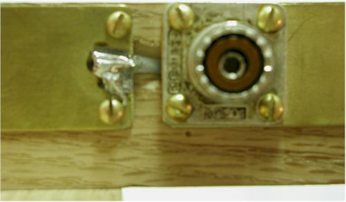
View of Connector
WA5SWD’S Direct Feed 50-Ohm Antenna - Photo 1
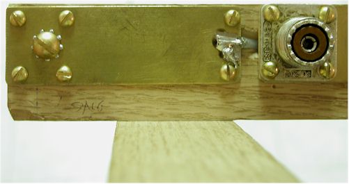
View of Long End
WA5SWD’S Direct Feed 50-Ohm Antenna - Photo 2
View of Short End
WA5SWD’S Direct Feed 50-Ohm Antenna - Photo 3
Testing
Mount the antenna in a clear location. I have found that you can be quite close to the antenna as long as the bottoms of the elements are above your head. Stay at least twenty inches away horizontally if possible. Attach your feedline and SWR indicator. Expect 1.1:1 or better at near 146 MHz. Expect 1.4:1 or less at the band edges. Try one or two coax turns around the support shaft to see if it helps. If you don’t get similar results, check your work again, locate and fix the problem.
Testing Results
I used my MFJ 239B to check the match on this antenna. This time I did not go to the trouble of making 1/2 wl cables. The results from before on the original version convinced me that this was not really a critical issue. With the rod lengths as shown, I had a 1:1 match at 146.34 MHz, 1.3:1 at 148 MHz and 1.3 at 144 MHz. These tests were done outside on a metal rail on an apartment complex stairway and should be fairly representative of the average installation.
Similar tests were repeated inside my apartment, and the SWR was slightly worse with the best match frequency dropping down to 144 MHz. The match was still acceptable for safe operation.
I noted there were indications of some current on the outside of the coax shield. There were slight changes in the SWR curves when I went from a one-turn ‘choke balun’ to a two-turn ‘choke balun’. A ferrite core over the shield on the coax where it attaches to the antenna might improve this.
While developing this antenna I had access to an RF Network Analyzer. With it I got results that essentially proved the accuracy of the MFJ-239B. The room I had available for test was far too small for lab grade testing with just over one wavelength clearance to some large metal objects. It did have better that 1/2 wl from the top of my antenna to the ceiling. Although the antenna experts desire at least 2 wl clearance, I think reasonable results can be had as close as one wl from large conducting objects. More is undoubtedly better but don’t think the results are without value with a bit less.
Remember: SWR is a measure of how much energy is coming back to the transmitter from the load. Go calculate how much that is for an SWR of 1.5:1. Then calculate how long the path length to a perfectly reflecting object the size of a refrigerator must be to give that level of power returned to your antenna. Remember, this power is falling off at the inverse of the fourth power of the distance, not the inverse of the square of the distance. You just might be surprised at this.
For Those Who Insist on Adjustments
Okay, now you want to ‘tweak’ the design. I don’t recommend this but if you want to play with the design, then you may want to try this: cut each of the rods shorter than the listed values. How much shorter is at your discretion. Drill and tap both ends of your rods. Run brass screws into the extra tapped holes and tweak to your hearts delight.
So What Does This One Do Better?
With these slight modifications in the construction you will be able to build a better antenna with less cost leaving a bit more funding for other projects. It will be more reliable, which is a plus, and be more tolerant of the battering from the weather.
You can substitute brass plate cut to the same size as the copper on the PWB for the PWB, avoiding the problems etching solutions cause. You might even say this is a more “environmentally friendly” version, since we don’t have to worry about disposal of the spent etchant. And I think it looks better without the visual ‘lumps’ caused by the nuts!
Further Test Results
I have now tested my J-Pole with an HP Network Analyzer/ S-parameter Test Set. There are several ‘freebie’ low SWR areas, one being in the vicinity of 440 MHz. I’m not about to claim anything except that the SWR is fairly low there-about 2.5:1 or so.
I tried adding some 1/8th-inch radiators sized to the 440 band but there was too much adverse effect on two meters, and lousy results on 440-so I removed these modifications.
When I tried it in my apartment I was able to raise several of the local 440 repeaters on my new J-pole design with no apparent harm to my transceiver through a 25-foot RG-58 feedline. Naturally, two-meter operation is unimpaired. So the 440 performance may not be much, but it’s free!
Originally posted on the AntennaX Online Magazine by Edward Lawrence, WA5SWD