This is a most interesting story of how one ham managed to work around antenna restrictions in a very restricted neighborhood. It took a lot of work and careful planning, but he was able to operate and satisfy all concerned parties. There may be some ideas that will help others that are in a difficult situation such as he was.
The problems started when he moved into a rather exclusive area of one of our major cities. The restrictions prohibited any antennas that would detract from the “beauty and natural setting” of the area. On top of that, the real estate agent saw the ham call license plates and said that amateur antennas were absolutely forbidden. That sort of put a damper on the new home purchase for a while. He was also told that any flagpoles had to be either plastic or fiberglass and no more than 25 feet tall. So no flagpole verticals.
But there was enough room in the attic to squeeze a trap dipole for 20, 15 and 10 meters, this being a long time before the WARC bands came into being. This was not totally satisfactory as some of the rooms would have the ceiling lights come on when he was on the air. Another solution had to be found and one that would allow operation on the lower bands, since that is where he liked to operate. About this time, a severe lighting storm took place and some of the fiberglass and plastic flagpoles were vaporized by lighting. The architectural committee approved the erection of metal flagpoles, but again less than 30 feet (9.12 meters) tall. He put up a metal flagpole which was inspected and blessed by the committee. But, one problem was that it could not be attached to anything, except a ground rod.
So a brilliant idea formed in the mind of Ham X. He would build a gazebo in his back yard, with permission of course, and see what sort of antenna he could hide in that small building. In due course, the gazebo was built and some guy wires were attached to the top of the flagpole so Christmas lights could be hoisted up to the top of the flagpole. All of which was approved by the committee. Ham X also got permission to put an underground sprinkler system in his back yard near the gazebo with the system controls hidden inside the gazebo.
After all of this was done, a rather destructive storm hit and several sheds were damaged in other folks’ yards. Some were shredded and thrown all over the neighborhood. Ham X then went to the committee and requested permission to use guy lines to tie his gazebo firmly to the ground. Permission was given and the gazebo was guyed down firmly. There was even permission given to put planters extending out from the corners of the gazebo in order to cover some of the sprinkler system tubing.
Everyone thought the gazebo was very attractive and the only thing missing was a weather vane lightning rod with a rooster on it. The committee said that was fine, even though it exceeded the maximum height allowed. A variance was granted to install the weather vane.
Lorem ipsum dolor sit amet, consectetur adipiscing elit. Ut elit tellus, luctus nec ullamcorper mattis, pulvinar dapibus leo.
Little did anyone suspect that gazebo had a rather intricate antenna built in it. The sprinkler controls hid a matching network and the flagpole was the vertical part of the antenna, The guys from the flagpole and those that held the gazebo down were also part of the antenna. They were tied together inside the gazebo along the roofline and where the guy wires came down to the ground anchors. These lines were all insulated from ground and went back inside the gazebo under the planters and then were all tied together at the feed point.
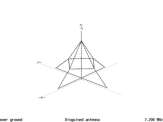
Figure 1 is the electrical diagram of the antenna, without the gazebo that surrounds it. It resembles a rectangular tower of very short and wide proportions and the feed point is at the base of the vertical flagpole element. The guy lines extend 21 feet (6.384 meters) and the cross connections between the guy lines is 10.6 ft.(3.224 meters) long and are that high above ground. The flagpole is 32 feet (9.728 meters) tall. All of the wiring was done with #12 solid copper wire, and painted over if it was inside the building. The matching network was a reversible L network and was concealed inside the remote controls for the sprinkler system.
A Really Disguised Antenna - Figure 1
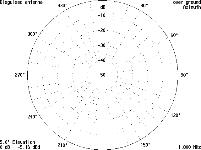
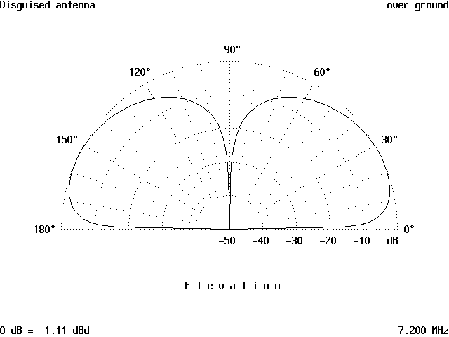
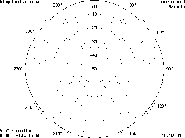
So how did it work? Very well indeed. Ham X was able to work all the bands below 20 meters, to include 160 with excellent results. Running the antenna on AO6.5 gave the following patterns. Figure 2 is the horizontal pattern on 160 meters and is a perfect circle, Figure 3 is the vertical pattern of the antenna and shows that the angle of radiation is at 24 degrees with -.46 Dbd. This is a good low angle of radiation for 160 meters and the results that were obtained indicate that. -.46 Dbd isn’t enough signal loss to even consider.
A Really Disguised Antenna - Figure 2
A Really Disguised Antenna - Figure 3
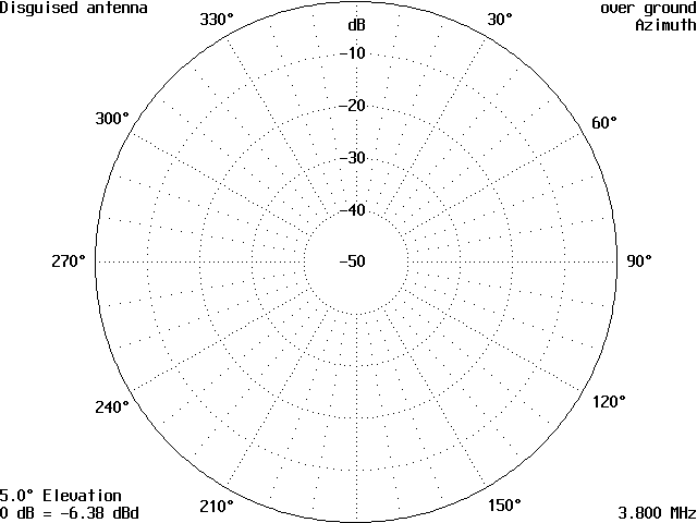
Figure 4 is the horizontal pattern for 75 meters and also is a circle and Figure 5 is the vertical pattern. The angle of radiation is at 26 degrees and is also a good low angle compared to a low dipole on this band. It also gave good results on DX contacts and the -1.03 Dbd is not enough to make a difference either. Certainly, there are antennas on the air on both 160 and 75 meters that are worse than this. So this is a good antenna for DX on these two bands where decent antennas are hard to come by.
A Really Disguised Antenna - Figure 4
A Really Disguised Antenna - Figure 5
Figure 6 is of the 40 meter horizontal plot and it is also a perfect circle. Figure 7 is the vertical pattern and shows that the angle of radiation is 24 degrees making the antenna also a DX antenna on 40 meters as well. The patterns on 30 meters were identical to the 40 meter ones. The only difference was the angle of radiation dropped to 23 degrees and the antenna was down by -1.43 dBd which again is not much to worry about.
A Really Disguised Antenna - Figure 6
A Really Disguised Antenna - Figure 7
On 20 meters, the patterns were the same as the previous ones and are not shown, except that the angle of radiation dropped to 19 degrees and the antenna is down only -.63 from a dipole. Again the antenna is a good one for DX due to the lower angle of radiation. The antenna did perform admirably on DX stations here.
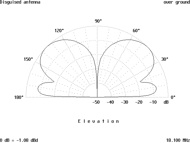
Moving on to 17 meters, the horizontal pattern in Figure 8 resembles a rounded square and this is due to the radiation from the guy wires. The vertical pattern in Figure 9 shows the antenna has an angle of radiation of 44 degrees and is down -1.08 from a dipole. The angle of radiation is starting to increase and this is not good for DX on the higher bands.
A Really Disguised Antenna - Figure 8
A Really Disguised Antenna - Figure 9
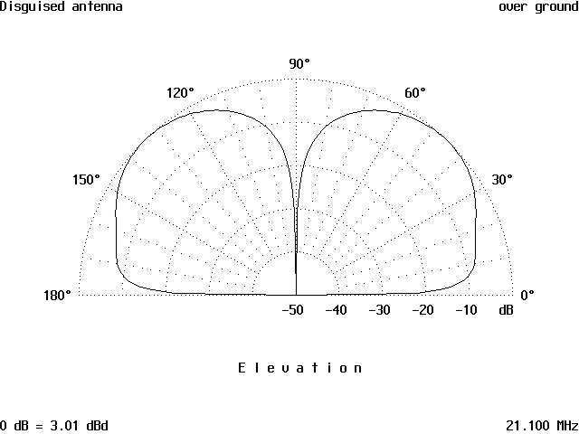
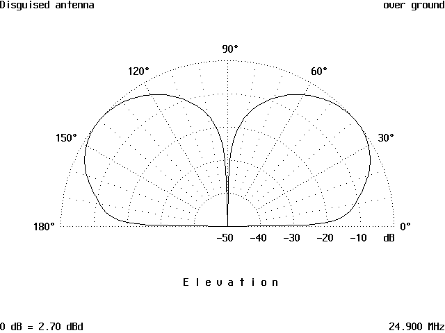
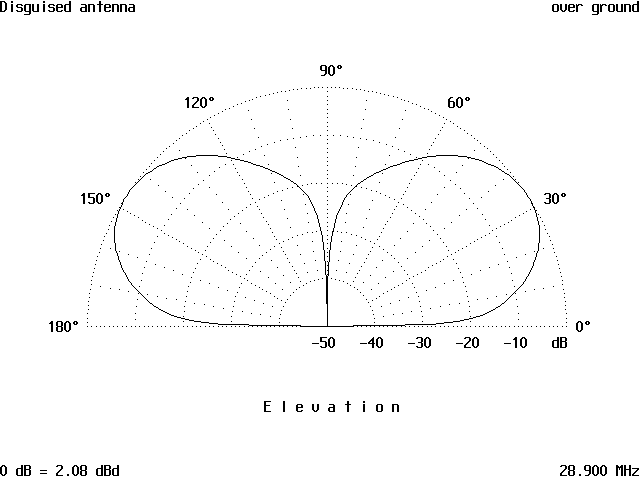
On 15 meters, the horizontal pattern is a circle again and the vertical pattern has increased its angle of radiation to 46 degrees at +3.01 dBd and this is not very good for DX. Figure 10 is the vertical pattern for 15 meters. Moving on to 12 meters, the horizontal pattern is still a circle and the vertical pattern in Figure 11 has dropped to 39 degrees and has a gain of 2.70 dBd, again still a very high angle of radiation. This indicates that on 10 meters the antenna will have a very high angle of radiation as well and Figure 12 shows that this is true. The angle is 33 degrees with 2.09 dBd gain.
A Really Disguised Antenna - Figure 10
A Really Disguised Antenna - Figure 11
A Really Disguised Antenna - Figure 12
So the really disguised antenna worked well where it was supposed to and is still working because Ham X has not moved since this antenna was constructed some 25+ years ago. The 160 to 20 meter bands are where Ham X wanted to work, and he has since added s small loop of 2.4 feet (.608 meters) diameter in his attic with a ground plane under it for the 17-10 meter bands. But, remember this is a story about Ham X’s solution to his particular discreet antenna needs and antenneX does not recommend schemes or methods that would be unlawful or offensive to others. We can tell the stories though.