My Attic CFA! The Mark II Crossfield Antenna
The Mark II Crossfield Antenna, by Alec Anderson, GD3HQR, appeared in the Autumn, 1993 issue of SPRAT, the Journal of the G-QRP Club. The article caught my attention since I was restricted at the time to a random length end-fed antenna tuned against various counterpoise wires and hidden in the roof storage area of our condo. This ‘tiny’ Crossfield antenna (approximately 20″H x 12″W) intrigued me since it provided multi-band operation, from 1.8 MHz through 30 MHz, construction didn’t look too difficult and I already had two of the components: a discarded 28 oz. can measuring 4″ in diameter and 4-1/2″ long and a 12″ pizza pan. [Ed: Note, the spelling “Crossfield” is purposely used in the original article is retained here even though the CFA is spelled Crossed-Field.]
The Hybrid Phaser circuit
The Hybrid Phaser circuit called for can be traced back to Anderson’s article in the 1992 G-QRP Club Antenna Handbook, “The GD3HQR 9-Band Hybrid Loop”. In it he states, “This is my variation on the crossed-field antenna (Electronics and Wireless World, March 1989). Instead of the short cylindrical form suggested in that article the radiator is a loop, thus considerably simplifying construction.” He then goes on to describe testing loops of various sizes from 2 feet (.6m) square to 12 feet (3.6m) square and comments that the larger loops, as expected, gave the best performance. Changing from a 12-foot square loop in the loft to a 2-foot square loop in the shack typically gave a drop of 2 S-points. The loops were made from standard antenna wire, electrician’s earth wire, and 300-ohm ribbon with the conductors connected in parallel. They all worked with powers up to 50 watts. These loops were all fed with coax having a minimum length of fifteen feet, the braid of which was not grounded.
The construction diagram of the antenna is shown in Figure 1. Aluminum flashing is readily available in various widths and lengths from 10 to 50 feet (3 to 15m). However, it is rather thin, and if planning to use the antenna outdoors, I would opt to try working with copper which can be obtained at hobby stores in 4 x 10 inch (10 x 25cm) sheets in various gauges. The dimensions of the antenna lend themselves to soldering with appropriate lips bent as required.
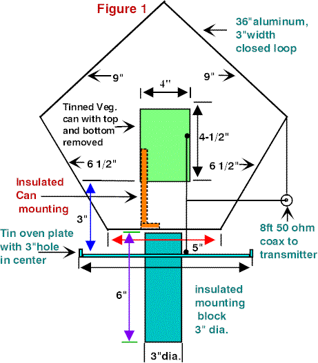
The aluminum flashing I used for the closed loop was scored along its length with an awl to give the structure more rigidity. A 6″ (15cm) length of 3″ (8cm) OD PVC pipe was used to position the 5″ (13cm) base of the closed loop. Four ceramic insulators anchored this base to the plate. A phonograph plug was secured to the flashing instead of an SO-239 to reduce weight and fatigue.
As can be seen from the schematic, (see Figure 2) construction of the phasing unit is fairly simple. L1 and L2 are each 7 turns of stranded, insulated wire bifilar-wound on a T200-2 Toroid (see supply source below). Note the direction of the windings. C1 and C2 are 365 pF capacitors insulated from ground. Again, be aware that the screen of the coax to the antenna is NOT grounded.
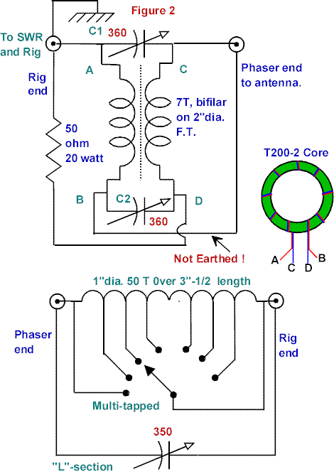
The Phasing Unit
The phasing unit was built into a compact wooden cabinet containing a 0-50 micro-ammeter RF current indicator and a copper sub-chassis to mount its sensitivity control, the unit’s input/output connectors and provide a ground connection for the 50-ohm resistor. The RF current transformer is a T68-2 iron powder toroidal core wound with 10 turns of #26 enamel wire for the secondary. The primary is made by passing the antenna lead or feedline through the core center. With coax feed it will be necessary to pass only the inner lead through the core. Voltage is measured across a 270-ohm resistor (see Figure 3).
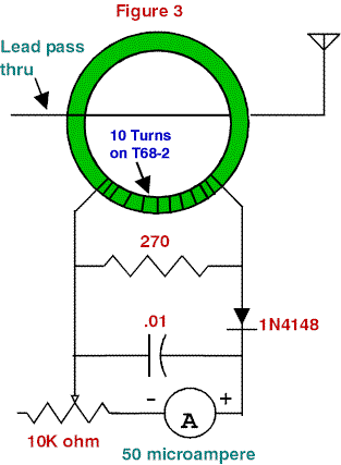
The proper sequence for the units following the transmitter is, first an SWR Meter, an Antenna Tuner (herein described as an L-network but I’ve had success with both a T-match and a Z-match) and finally the Phaser with the braid on the output ungrounded. In my assembly I made certain that the inside of the braid makes contact with its connector. Also, I find no need to mount the phasing unit under the antenna. In tests, I had ten feet of coax from the phaser to the antenna, and in the final installation, there’s approximately 30 feet (9m) of coax in the feedline. This was necessary since our house is aluminum-sided and it was decided to place the antenna in the attic near roof level in an attempt to reduce shielding.
In preparing this article, I sought to verify the phasing unit, so I built a CFA based upon the parameters indicated in the construction article by Richard Morrow, K5CNF, but eliminating the ground plane (antenneX construction article, “CFA Construction Guide for 75/80 Meters” now in Archive III). It was a simple assembly, using a 6″ (15cm) diameter coffee can, its plastic cover as an insulator and aluminum foil cut 12″ (30cm) in diameter. Again, Anderson’s phaser proved its worth. I made five contacts ranging from 114-592 miles on 40 meters with 4 watts input on CW with the antenna next to me at the operating position.
Valve type rigs with tunable pi section outputs may not require the L-network but it is essential when using transistor rigs with fixed-tuned half wave filter outputs. To tune the loop, adjust the L-network for maximum received signals on the desired band. Using low power, adjust C2 in small steps, at each step adjusting C1 and the L-network for minimum SWR. When the lowest SWR is found, record the settings for future use. Repeat for the other bands. Covering the whole band on 1.8 and 3.5 MHz probably will require readjustment of the phasing capacitors and the L-network. Placement of a 3-foot (.9m) square sheet of metal (not grounded) under the base will improve high angle radiation for short skip contacts on 3.5 and 7 MHz.
Assuming that for a given system of antenna and feeder and constant transmitter output power, the RF current at a given frequency is proportional to the radiated power. Any increase in current caused by better tuner/phaser efficiency is evidence of an increase in radiated power. RF current meters, usually thermocouple devices, were popular for tuning antennas before the SWR meter. These meters are now very rare and hard to find. The current transformer I’m using on the output lead (C on the T200-2 core) can be used for any antenna or feed system, although if exactly an electrical half wave (or multiple) from the end of the radiator the current may be too small to register.
If a range of inductance and capacitance is available in the tuner, try different settings to find the combination that gives maximum antenna current at match. On various bands, and even at different frequencies in the same band, this current reading will vary. Absolute value does not matter, what is important is to find the tuner configuration that gives maximum antenna current under matched conditions.
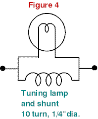
A small lamp with a shunt (see Figure 4) can also be used as a substitute for an RF ammeter. The lamp for indicating maximum current depends upon the output power. Use a 60 ma., 2 volt pilot lamp for 2-5 watt QRP and a 250 ma., 6 volt lamp for 100 watt input. The shunt is made of 10 turns, 1/4″ (.6cm) diameter, #20 or 22 solid, insulated wire connected in parallel with the lamp. Most of the current goes through the shunt and only enough goes through the lamp to light it. Since the brightness of the lamp is proportional to the actual RF current in the line, any tuning condition that results in maximum brightness is the one giving the greatest power output.
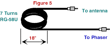
Since my antenna is mounted in the attic and surrounded by grounded conduit, cables, fixtures and pipes, a decoupling loop (see Figure 5) was incorporated which consists of 7 turns of RG-58U wound into a coil 18″ in diameter (good for 160-10 meter use, per Wes Farnsworth, KE0NH, S.K.). RG8U is not recommended, as it is not “leaky” enough at HF frequencies to act like a transformer. It’s important that the coax in the coil not cross over itself. Wooden clothes’ pins are used to secure the coax and prevent it from crossing over. We stabilized it with tape and mounted it at the base of the antenna. The coil decouples the antenna from ground and makes it act as a free antenna floating in space. This system works remarkably well on all bands with an SWR that does not exceed 1.5:1 as measured with an Autek RF Analyst RF-1.
Antennas are still one facet of our hobby we can delve into with enthusiasm and know we’re not going to break the family budget or get stuck with a project half completed. We all read and imagine our skywires on lofty masts with lots and lots of real estate to spread them out. When reality sets in it’s nice to know some of these compact designs DO work and the convenience of working indoors has its rewards. I’m not going to give up my 102′ (31m) center-fed multiband dipole but I do want to encourage those reluctant to build some of the various antenna concepts and designs presented in antenneX to try your hand and experiment. You’ll be richly rewarded with the knowledge and experience gained!
In my correspondence with Mr. Anderson I asked about the principle of operation, and he replied, “My original Crossfield was just an idea to make a very small antenna that could be used indoors or at ground level and mine worked well.” I’m very grateful to this fine gentleman and am also proud to say, “mine works great as well!” and leave the theory to those more proficient in the subject. Take a look at these pictures of my attic CFA, the phaser and some equipment used and see if this may be a solution for your QTH:
Originally posted on the AntennaX Online Magazine by Dick Jones, K9ZNZ
Last Updated : 14th May 2024
