A Giant 40-Meter Wire Beam
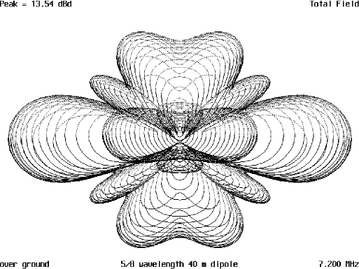

This is one of those antennas that came out of a what-if? session with Ted Hart, W5QJR some time ago. We were talking about what kind of antennas would give some real gain on the lower frequencies and he suggested a collinear array made out of 5/8 wavelength elements with the bottom elements 1/2 wavelength above ground and the top elements 1 wavelength high. Then, by making a four-element array with the second pair of elements besides the first, this should give an antenna with some gain. Exactly how much we weren’t sure. After modelling the antenna using AO6.5 I found out there was 13.54 dBd gain at 17 degrees elevation. This came from a combination of the elements being phased correctly and the 5/8 wave elements each had some gain to contribute due to the total gain of this type of antenna.
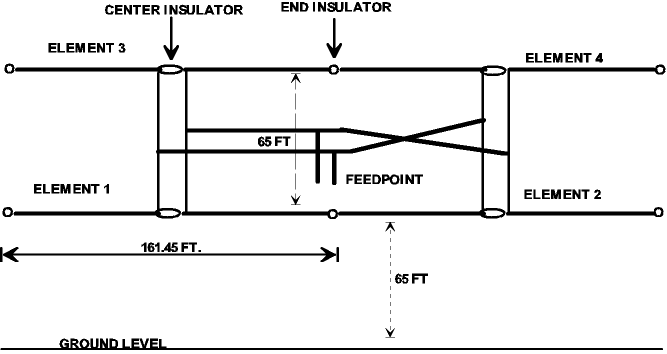
Figure 1 is the horizontal diagram of this antenna, and the beamwidth is exceptionally narrow. Approximately 20 degrees is what seems to show up on the pattern and is a very narrow pattern, both fore and aft, since this is a bi-directional antenna. Figure 2 is the vertical pattern, and this indicated the maximum is at 17° which is ideal for DX work on any band. Figure 3 is the basic construction of the antenna, less supporting structures.
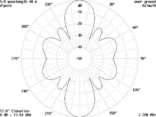
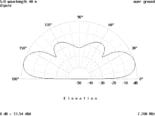
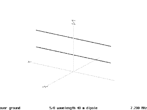
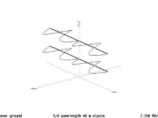
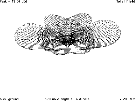
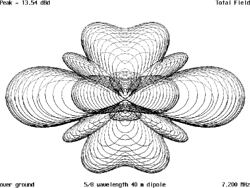
Figure 4 is of the antenna showing the current distribution and magnitude on the elements. Figure 5 is the 3D pattern viewed from the side and slightly to the left of a right angle to the centre of the antenna and up about 30 degrees. Figure 6 is directly above the centre and is also a 3D representation. Figure 7 is a possible construction idea.
Feed point Impedance at Each Element
Again, this is one huge antenna being 130+ feet high and close to 400 feet across. If you can put one up, I can guarantee you will be king of the hill in any part of the 40 meter band that you want to operate.
Originally posted on the AntennaX Online Magazine by Richard Morrow, K5CNF
Last Updated : 25th February 2024
