A 3 Element Tri-Band Beam with 2 Active Elements on Each Band
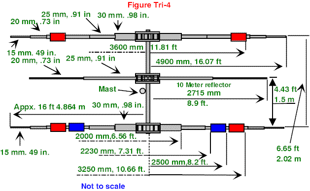
This antenna is an extension on the earlier described 2-element tri-band beam. Now I have extended the antenna with a reflector for each band. The reflector for 10 meters is full size; the reflector for 15 and 20 is a dualband type. Now the reflectors have an optimum distance of about 0.15 l for 10 and 15 meters.
The F/B ratio with this antenna is about 12 dB for DX and 25 dB for the groundwave (measured with a rather good S-meter). The bandwidth is relatively small (optimized for CW). The first time I used the antenna was in the 1987 PACC contest and the results were very good. I have considered making full-size reflectors for 15 and 20 meter, but at that time it would make the antenna too large.
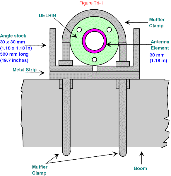
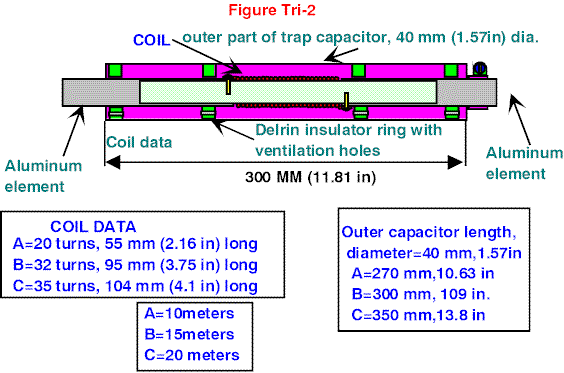
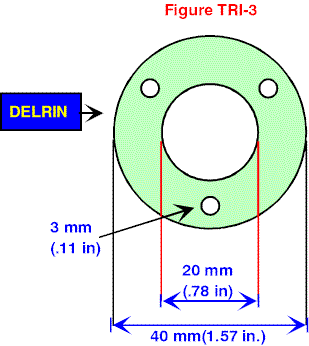
The material is standard aluminum from a local hardware store. The rings in the trap are made from Delrin. You can also use nylon, Teflon or similar material. The coil is made of standard electrical housing wire (2,5 mm2). (#10 or #12 AWG will do) The element to boom support is made of angle stock. The elements are connected with muffler clamps to the boomplate and the tubes and traps are connected with hose clamps. On the underside of the traps, some holes prevent moisture to stay in the traps.

Tune as Follows
Try to tune the antenna as high as possible above the ground, on a small ladder or on the balcony. First tune the dipole for 10 meters with transmitter and SWR meter connected directly to the dipole, or via a dip-meter and impedance bridge. Then connect the traps (see figures) with a short piece of aluminum tube to the dipole. Now the outside of the dipole with the traps must have the same length as the original dipole before the traps where connected. Now slide the outer tube of the traps until you get a good SWR / impedance. You can eventually change the length of the dipole to get a correct SWR.
Editor’s note: If you support a beam reflector a couple of feet above ground with the beam pointing roughly straight up, the element tuning and VSWR will be the same as when the beam is mounted high up on a tower.

Connect the correct length for 15 meter to the traps and tune for 15-meter resonance. Then again connect the outer tip for 20 meter with the traps and tune again for 15-meter resonance by sliding the outer tube until resonant. Finally tune for resonance at 20 meters. This whole procedure will take you quite some time, but it is very important to work step by step!
The tuning is very critical—one-half a centimeter (1.27 inches) has big influence on the resonant frequency.
Next, connect the reflector. The SWR has some influence on the resonant frequency of the dipole. Now tune for optimum F/B ratio. This is done by first making the reflector as a dipole and tune with the dip-meter the resonance frequency about 5% lower than the resonance frequency of the dipole (desired frequency).

Then connect the reflector halves again. Now you are ready to try the antenna.
The best way to tune is to use a field strength meter on some wavelength’s distance of the antenna. Tune for maximum F/B. You can also try to tune on a signal from your neighbor ham. When he sends a signal, you can tune with a diode probe for optimum or minimum signal.
The greatest challenge for building the antenna will be the mechanical part (and tuning). You also can try to build the traps with coax cable. My antenna was in the air for more than five years before I built a monobander (next article). It survived the Dutch storms, humidity and ice rampant here in the Netherlands. After disassembling the antenna, there was no sign of corrosion on the traps (copper with aluminum) because I sealed the connections with silicone!

Originally posted on the AntennaX Online Magazine by Kees Wiegers, PA3BHS
Last Updated : 16th March 2024
