The Dipole Antenna, Simple and Versatile
A good example of the phased dipole antenna is the use of phased dipoles for a DX antenna on 40 meters. This antenna is at a height of 64 feet and consists of two dipoles ¼ wavelength apart and the two antennas are fed 180 degrees out of phase. The resultant antenna has 5.2 dB gain at a vertical elevation angle of 31 degrees. The vertical pattern in Figure 1 shows the antenna is bi-directional with the gain apparent in both directions.
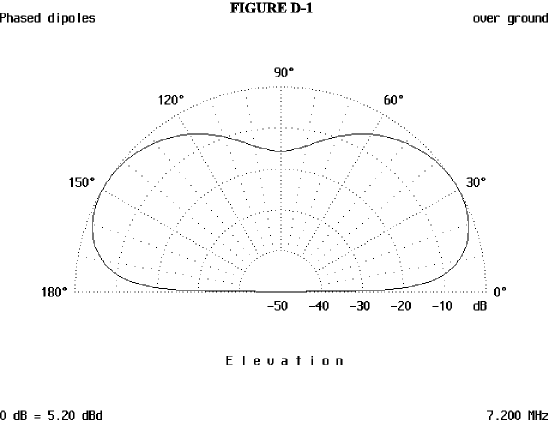
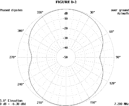
This allows the antenna to be put up to cover any two areas of the world you may need to put a signal into to get DXCC or work that rare Dx-pedition. Figure 2 is the horizontal pattern and the null off of the sides are down about 15 dB. This pattern was run at an elevation of 5 degrees so the gain figures are not as high as they are at 31 degrees which is the peak of the major lobe.
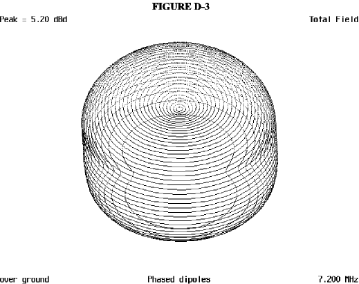
The 3D antenna pattern in Figure 3 is viewed from straight on and if you start at the nulls at ground level, you can go up the sides and that shows how the nulls start to vanish as the pattern moves toward the vertical. When the angle reaches approximately 60° the pattern then becomes an oval. This has no effect on the overall performance of the antenna. There is also a dip in the pattern at 90°.
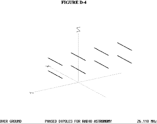
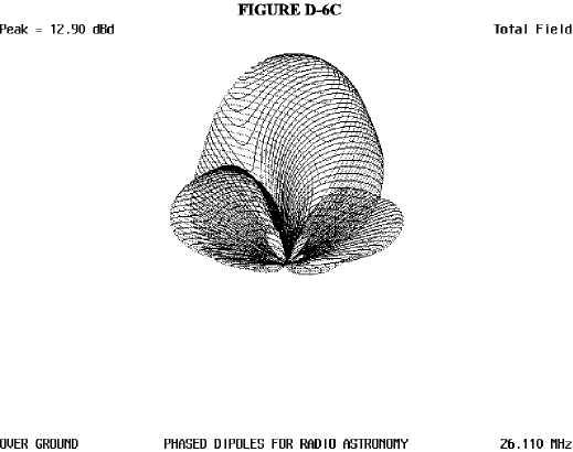
Another example of the versatility of the dipole is the array pictured in Figure 4, an array used for a radio telescope on 26.110 MHz. This particular array will allow the reception of signals from the planet Jupiter. Jupiter radiates a series of static crashes that seem to be coming from the storm that has raged for hundreds of years on the surface of the huge planet. This antenna was designed for the fun of it. Figure 4 is of the array. This is an array of eight dipoles with the bottom dipoles fed 90 degrees out of phase from the top ones. Figure 4 is of the array less the supporting structures.
In Figure 4a, the vertical pattern of the array shows how the major lobe of this antenna is straight up. It could be possibly improved by the addition of reflectors and directors, but since this array was only a interesting project, this was never tried. You will notice the gain of this array is 12.92 dBd straight up. By modifying the array so the antenna would radiate in a more normal manner and changing the antennas to operate on 10 or 12 meters, this antenna would enable even a low power signal to almost rule the band.
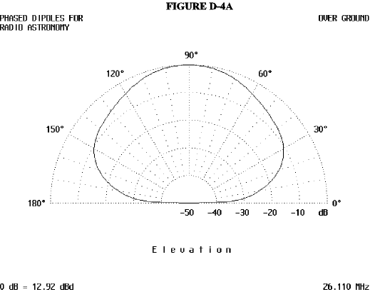
Figure 5 is of the horizontal pattern at 5 degrees and there is no gain at this elevation and it would be useless for most terrestrial communications
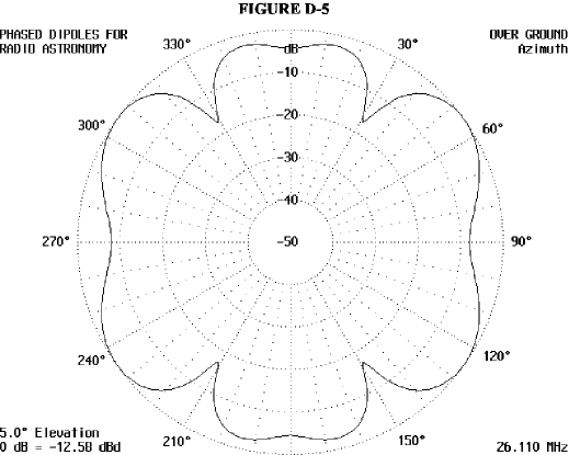
Figure 6a is a 3D view of the pattern and is the X-axis view. The vertical pattern is very narrow in this view, and the two very minor lobes are seen to be very small in comparison to the major lobe.
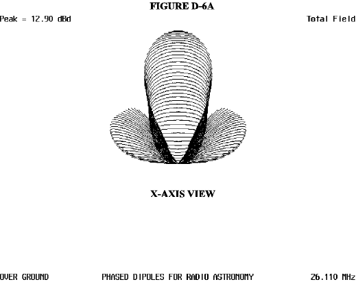
Figure 6b is the Y-axis view and illustrates the heart shape that is also visible in the standard polar plot. The minor lobes are also visible and their much smaller size is readily apparent.
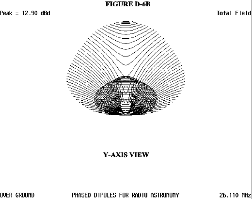
Figure 6c is from an oblique angle and the general shape of the pattern can be seen very well.
Another dipole variation is the W8JK array. This array was designed by WJK and consists of two dipoles spaced 1/8 wavelength apart. This array can be made for any band and is very effective. The two dipoles are fed 180 degrees out of phase and the antenna is bi-directional.. For the higher frequencies, 20 meters and higher, the antenna can be rotated by a small rotator. It has a low angle of radiation and if the antenna is ½ wave length or more, the angle of radiation will be very low. In Figure 7, the pattern is of a 40 meter JK array and it has a vertical angle of 40°. This antenna was only 20 ft. high and if it were higher, it would have an even lower angle of radiation.
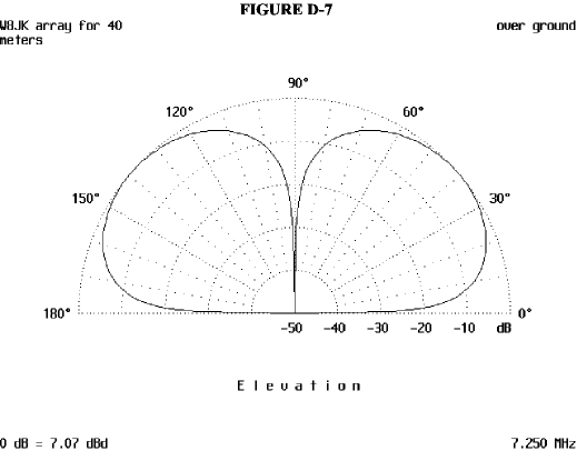
Figure 8 is a 3D pattern of the array and you can see the very deep null found at right angles to the antenna. This null is at all angles, from horizontal to vertical and very deep. It has a beam width of 69° and will be a very good antenna for DX even at this low height.

An interesting thing about the bi-directional antenna is that if you have a full break in CW mode, you can easily find an around the world path with these antennas. All you have to do is to send a few dits and if your rig recovers fast enough, you should hear the dits coming in from the rear of the array. If you don’t, then rotate your antenna about 20 degrees and then send a few more dits. Keep this procedure up, identifying your station as you go, until you hear your own signals coming in from behind you. Then you will have found the path around the world. Of course, this all depends on propagation, but the ability to do this can be nice to have.
Another dipole directional array is the ZL Special and it is covered in another antenneX article this month as well as in past issues. So it will not be gone into here.
The last antenna we will look at is a 10 meter dipole, at a height of 34 ft. This is a rotary dipole and a single element antenna. At this height, there is some gain due to reflection from the ground and the resultant phase addition that takes place. Figure 9 is the horizontal pattern and shows a beam width of 79° This is a 16.8 ft long (5.1 meter) half wave antenna.
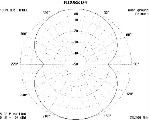
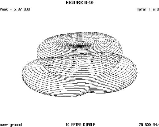
Figure 10 is the 3D pattern of the antenna and shows that the null at ground level (5°) there is a null and the null gradually disappears as the angle towards the vertical increases.
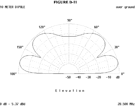
The pattern in Figure 11 is the vertical radiation of this antenna and at the 14° angle, there is a gain of 5.37 dBd. This is pretty good for a simple antenna and the secondary lobe at approximately 45° is down about 2 dB from the major lobe. This is not too bad as there is a good chance this will enable you to hear some stations are closer.
So now you have seen some of the variations on the dipole that you may not have been aware. It may be simple, but it has been around for many years and will probably continue for many more.
Originally posted on the AntennaX Online Magazine by Richard Morrow, K5CNF
Last Updated : 14th March 2024
