
High Performance Low Cost DX Antenna
Defining the Problem
My problem, simply stated, is that I have friends 400 miles south and others 780 to 920 miles west. This corresponds to antenna take-off-angles of 40 and 18 to 22 degrees respectively. Therefore, I want to have a very good 40 meter antenna that places an exceptional signal at 400 miles south of my new QTH and also an exceptional signal centered about 850 miles to the west. The remainder of distances and directions are in the “I don’t care, I’ll take what I can get” category. My 1/2 wave vertical (See July 1998 antenneX – An Uncommonly Good Vertical) does well at 850 miles to the west, but not as good as I would like 400 miles to the south. That is just a little too close for a good vertical. By sloping the vertical I got good but not super performance both places, but I am always looking for a better antenna.
Summary Results
Did I achieve my objectives ? You bet—and came up with a super DX antenna as well! You may not choose to build one, but there are great tidbits to chew on, so read on. This one ain’t like nothin you never seen before.
40 Meters is a good daytime band for me. I could have picked other bands but the type of antenna for the specified distance would be the same. To make an easy conversion, this article will talk about dimensions in wavelengths, with a chart at the end to convert to feet for the various bands.
Note that I defined the desired radiation pattern of the antenna as the first step in the design process. Now we can work the problem by selecting the antenna that has the desired pattern. Unfortunately, I don’t know of one that is optimum at both the specified distances and directions, so we have to be a little creative.
Design Process
I know a horizontal dipole is good at 400 miles, but how good? The first step is to determine the optimum height. I looked at the HF Link Analyzer Sliderule and it told me I needed a takeoff angle of about 40 degrees. The optimum height turns out to be about 0.4 wavelength, based on the chart in the book entitled The Rules of the Antenna Game (see the Shopping Shack). Using the same process for 850 miles the height needs to be about 3/4 wavelengths. One potential solution is to put up crossed dipoles, one running North/South at a height of 3/4 wavelengths and the other oriented East/West at a height of 0.4 wavelengths, thus placing the broadside of the dipoles for maximum signal in the desired direction. At 7.2 MHz that translates to physical heights of 102 feet and 55 feet (31 and 16.8 m), respectively. I have tall pine trees, but they ain’t that tall – time to reconsider.
The dipole at 55 feet will do a great job, and I know my vertical is good at 850 miles, but I hate to have to switch antennas. If there were a way to feed both from the same feedline I could create the desired pattern. Perhaps if I move the center of the vertical to 55 feet then the two antennas would have their high current feed points at the same height. That would make the top of the vertical (1/4 wave above the current feed point) = about 32 feet (9.8 m) on 40 meters + the 55 feet from above. That totals to 87 feet (26.5 m), just about right for my favorite Pine tree.
The actual height could be lowered, but then I would not have the desired optimum antenna. Remember, we are still in the design stage, so let’s don’t give up any performance we don’t have to. If this approach does not bear fruit, we have only lost a little time and scratch paper, because we have not yet begun to cut wire. The next step is to check this out on the computer (I use EZNEC) and see if it really will do what is desired.
Unfortunately, I was not able to combine the antennas in a manner that did not reduce the performance in one way or the other. By proper phasing, the dipole could help the vertical by creating a cardoid pattern with a null to the East. However, the pattern gain to the south was diminished.
From a performance viewpoint, it is best to use two antennas for the two different ranges and directions and switch between them. However, this was an interesting experiment and done in the comfort of an easy chair while banging on the computer. I did not string any wires and the answer from the computer left no question as to what might have been.
Results of the Dipole Design
According to the HF Link Analyzer Sliderule (available from the Shopping Shack) the dipole will provide a signal of about 15 dB over S-9 from my 100 watts at the desired 400 miles (assuming their antenna gain is only unity). That is good enough. For the other link, the signal is predicted to be only 5db over S-9. Good, but not great. That indicates the need to improve the 850-mile link. Please note the design of an antenna system is like eating an elephant – one bite at a time.
The Evolution of a Vertical Beam
I have a good vertical. Maybe another vertical as a parasitic element? The computer says that is good, but two parasitic elements are better, and after doing some simple mechanical design, I found the cost does not increase to have both a director and a reflector, since it only takes two (2) supports to hang three (3) wires. By adding two more posts, a steerable beam can be constructed. It would be very time-consuming to take you through the design process I just went through, including chasing down some blind alleys, so I will give you the benefit of the results without the distractions. While reading this, keep in mind the design is applicable to any band—only the length of wire changes—thus the height of the support posts. This beam only needs four (4) posts about 18 feet (5.5 m) tall to make a very good beam on 10 Meters. Fortunately I have a plentiful supply of pine trees to support a 40 Meter Beam.
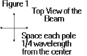
This beam, in it’s full implementation, only requires four (4) supports, each one being 1/2 wavelength tall and spaced 1/4 wavelength from the center of the antenna. Only two poles are needed if you choose not to rotate the antenna pattern. This is better described in Figure 1.
If rope is run from each opposing pole across the center, then a center feed element can be hung from the rope. That element needs to be exactly 1/2 Wavelength tall, and can be made of #14 wire. This is considered a wide-spaced beam but this was chosen to allow the use of wire for the elements, rather than heavy aluminum tubing, to minimize the cost. Parasitic elements significantly lower the radiation resistance of the driven element, thus increasing the loss. The amount of loss is a function of the spacing. Actually, the gain of a beam increases as the spacing between elements decreases. However, for close spacing, the loss increases faster than the gain. Thus, for normal beams a spacing of about 0.15 wavelengths is optimum.
For this design, hang four (4) director elements, one at each post, having a length of 0.46 Wavelengths. If the supports are 0.51 Wavelengths high, then the wires will hang down to 0.05 wavelengths above ground. Install insulators and secure the wires to keep them from blowing in the breeze. Note I stated you should install four (4) Directors. When it is desired to have a Reflector, then simply add a piece of wire 0.04 wavelengths long (a clip lead is great for this application) to extend the wire length to a total of 0.5 wavelengths.
The driven element, in the center of the array, always remains as a 0.5 wavelength element and is fed directly to a matching circuit or tuning unit located in the center of the array. This is a very high impedance feed and is fed relative to ground. Since it is very high, a simple ground rod suffices as a good ground. A couple of buried wires a few feet long won’t hurt, and should be installed as protection against lightning, whether they are needed for a low impedance ground for the array or not.
Performance of the Vertical Beam
Now that you have formulated a picture of the beam in your mind, the following performance values will certainly color the picture. The nominal 3 dB beamwidth of this antenna in the horizontal plane is about 90 degrees. That simply says it is necessary to be able to rotate the beam in 45-degree increments, which is readily done using clip leads to lengthen or ground various elements as required to steer the beam. The various configurations of the beam are as follows:3.
Beam pointing East: Make a Reflector of the West element and ground both the North and South elements. Due to natural causes, by grounding an element it simply disappears from the array. Thus, this configuration effectively is using 3 elements, with two missing. Again, it only takes a ground rod at each element, not a fancy ground.
If you desire a beam pointing west, make the West element a Director and the East element a Reflector. The following are performance figures as presented by EZNEC. It should be noted that very good ground conductivity was used in the analysis. Poor soil will reduce the performance figures 3 or 4 dB—certainly not enough to prevent the antenna from performing very well.
Performance of a three (3) element array
| Gain dBi | Front to Back dBi | El TOA Degrees | El 3 dB Beamwidth Degrees | Az 3 dB Beamwidth Degrees |
|---|---|---|---|---|
| 5.24 | 11.23 | 16.75 | 24.75 | 93 |
5 dBi gain for a 3 element beam doesn’t seem like much, until you realize this is a vertically polarized beam and we are talking low takeoff angles ideal for DX. It would take a heck of a stack of horizontal beams to match this performance—and it sure would cost a lot more. The reason it would take a stack of several horizontal beams is that several are required to fill in the nulls in the elevation pattern for horizontal antennas at great height. We are fighting ground loss at low take-off-angles to achieve DX performance.
Now look at the other numbers and note they are quite respectable. Again, the azimuth beamwidth is broader than a horizontal beam, which is typically about 60 degrees. You need to remember the azimuth pattern is orthogonal to the vertical elements, causing the greater beamwidth.
Beam Pointing 45 Degrees: This beam can be rotated in azimuth in increments of 45 degrees, thus providing a total of eight (8) positions. To direct the pattern North-East (45 degrees) it is necessary to do the following: Make Reflectors out of both the West and South elements. Also, make Directors out of both the East and North elements. The following is a performance summary for this configuration:
Performance of a five (5) element array
| Gain dBi | Front to Back dBi | El TOA Degrees | El 3 dB Beamwidth Degrees | Az 3 dB Beamwidth Degrees |
|---|---|---|---|---|
| 4.59 | 14.8 | 16.5 | 24.75 | 89 |
If you compare gain of the 3 element array to the 5 element array, the gain is reduced even though there are more elements used. That is because this is not a co-linear array. The front to back ratio did improve due to the extra elements.
What do you call this array with the end fed center element? I don’t have a good name for it and would appreciate recommendations for a name. In fact, I will send a free HF Link Analyzer Sliderule to the one that suggests the best name!
To point the beam in any desired direction, use the techniques described above. For any of the four primary directions, use 3 elements with the other two grounded. For beaming at 45 degrees to the primary directions, use all elements, with 2 directors and 2 reflectors.
To accomplish all of this, you need two clip leads to convert Directors to Reflectors, and two clip leads to ground directors. It would be difficult to use relays to switch the beam patterns due to the high voltages at the ends of the elements, even though the current is low. If someone could suggest the design of a high voltage relay that others could build, this could become a widely used antenna. Some of us couch potatoes don’t want to have to go out in the rain and rotate the beam. However, if you are a DX hound, you don’t know when and where the rare DX station will appear, and the entire effort of building this antenna to capture just one rare one will be worth the effort.
Summary
Looking back, maybe I did not accomplish my initial goal. I wanted an antenna pattern at a takeoff angle centered on 20 degrees, and this one is centered on 16.5 degrees. However, Mother Nature has dictated what you can do with a vertical antenna, so I will have to live with it. Since I will primarily be working West-South-West from my Georgia QTH, The pattern will peak out over Mexico and I have to suffer the extra QRM. But, since it is a directive beam, my receiver will be very happy not to listen to all the stations on the back and sides of the beam—so I won again.
Actually, I am not displeased. In fact, it is nice to develop a new antenna design that should help a lot of Hams, and I can use it to effectively communicate with my friends out west and make new friends in other directions.
There are two things to consider while reflecting on this article:
- It would be interesting to load the elements (with loading coils) to reduce the height required for the supports. If someone does a computer analysis on this subject, please report it to antenneX so it can be shared with others. I have my own ideas but have not had time to implement them. When I do, I will share them with you.
- With shortened elements (and remote relays) , this array could very well become a preferred antenna for a lot of Hams.
Hope this antenna helps some of you.
Appendix
This appendix contains additional useful information including radiation patterns developed by EZNEC. The following chart converts wavelength versus frequency to Feet for the various bands.
| Frequency (MHz) | Half Wavelength | Quarter Wavelength | 0.04 Wavelength | 0.01 Wavelength |
|---|---|---|---|---|
| 7.2 | 68.33 ft | 34.17 ft | 5.47 ft | 1.37 ft |
| 10.1 | 48.71 ft | 24.36 ft | 3.90 ft | 0.97 ft |
| 14.1 | 34.89 ft | 17.45 ft | 2.79 ft | 0.70 ft |
| 18 | 27.33 ft | 13.67 ft | 2.19 ft | 0.55 ft |
| 21.3 | 23.10 ft | 11.55 ft | 1.85 ft | 0.46 ft |
| 24 | 20.50 ft | 10.25 ft | 1.64 ft | 0.41 ft |
| 29 | 16.97 ft | 8.48 ft | 1.36 ft | 0.34 ft |
Originally posted on the AntennaX Online Magazine by Ted Hart, W5QJR
Last Updated : 22nd April 2024