CFA Feed Lead Length
During last month’s laboratory experiments I discovered that lead length has a profound effect on the CFA tuner by adding unknown reactances and phase shifts into the circuit. This greatly confuses the issue of tuning the CFA. This month I designed a circuit with the shortest possible lead length, and with leads in positions that associate their inductance with a larger inductance designed into the circuit. The process is described below and the result is a circuit that acts more like my preconceived notions of how an antenna should behave than any other circuit tried so far. Thus, it has an SWR of 1:1 at resonance; the receiver noise peaks at the same frequency as the 1:1 value; the field strength when transmitting also peaks at the same value. It is tunable from about 2.2 MHz to above 7.5 MHz, and the SWR tuning curve looks the same at the transmitter as it does 75 cable-feet away at the antenna.
I started the experiment by remembering that at least one Egyptian CFA is fed at the outer edge of the D plate, so I mounted the input connector about 1 inch (2.54cm) from the edge of my 12-inch (30cm) diameter D plate. The plate has a capacitance of about 525 pF, and a spacing of 1/8 inch using a sheet of Lucite as a dielectric. The D plate forms the input capacitance of a pi-section tuner.
The coil for the pi section is soldered to the edge of the hole in the D plate and to the bottom edge of the E plate cylinder with leads about 1 inch long. The coil inductance is 9 uH, wound on a 2-inch (5cm) diameter PVC pipe about 2-1/2 inches (6.35cm) long and sits below and partially inside the E plate cylinder. The last lead is about 6 inches (15cm) long, and goes straight down from the E plate edge where the coil is connected through the hole in the D plate and a hole in the ground plane to the tuning capacitor under the ground plate. That capacitor is about 500 pF at maximum setting.
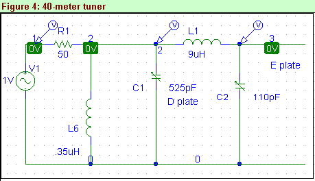
The pi section alone looks very capacitive at the cable connector when adjusted so that the SWR is minimum. It is resistive only at the resonance, which shows as a deep null that indicates a load much less than 50 ohms at the connector. To correct this reactance, a small coil is placed in parallel with the D plate. The admittance of the coil adjusts the admittance of the pi section to give a net of 50 ohms resistive at the 0.5-volt level near the null, resulting in an SWR of 1:1. The value of the coil is 0.75 uH for 80 meters, and 0.35 uH for 40 meters. It also serves to move the frequency where the phase shift between the D plate and E plate voltages is 90 degrees to the value where the SWR is 1:1. The small coil is about 1-1/2 turns for each half, connected around a rotary switch mounted about an inch from the connector to switch from 80 meters to 40 meters.
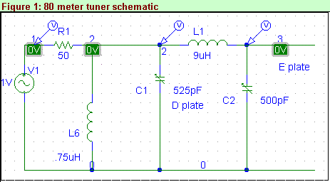
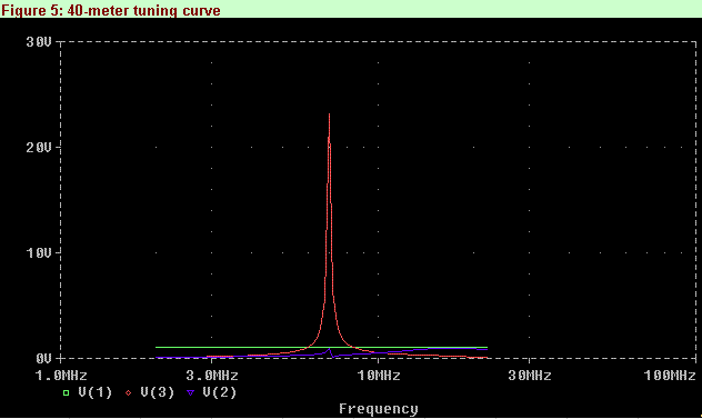
The circuit is shown in Figure 1. PSpice software renders the curves shown in Figures 2 and 3 for 80 meters, and Figures 4 – 6 for 40 meters. No attempt has been made to get the voltage ratio between E and D plates to the desired ratio, since I had no way to predict how the 377 ohm space impedance would affect the circuit. Figure 2 is the basic data from the circuit simulation. It shows the generator voltage (green, 1 volt), the E plate voltage (red, v3), and the loaded transmission line input voltage to the CFA (blue, v2). All are plotted over a frequency range from 2 to 20 MHz.
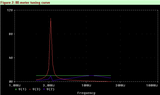
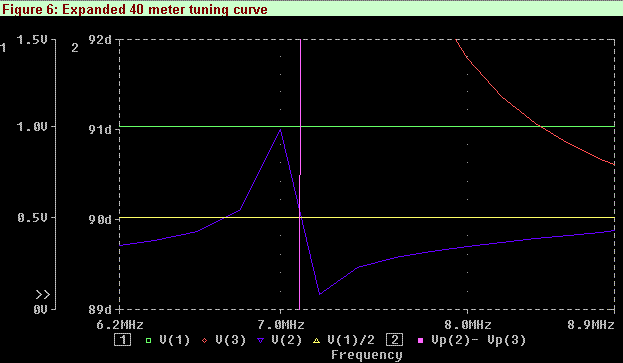
Figure 3 is an expanded subset of Figure 2, showing the same 3 voltages plus two calculated ones: the phase between the D plate and the E plate (purple, scale 2) voltages and the voltage that corresponds to a 50-ohm load at v2 (yellow). Note that the degrees scale (axis 2) goes between 89 and 92 degrees. The phase between the D plate and the E plate changes rapidly with frequency at the 1:1 SWR frequency, giving an almost vertical line that clearly shows the 90-degree phase difference frequency and its position at the frequency where the 1:1 SWR occurs.
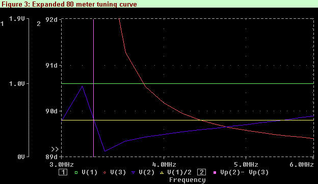
The red E plate voltage is in the corner of Figure 3. Figure 4 shows the component values that tune the CFA to 40 meters. Figure 5 is the basic data, and Figure 6 is an expanded view of Figure 5. The voltage ratios between the E plate and the D plate are 21.6 and 50 for 80 and 40 meters respectively. At 50 watts the D plate voltage is 50 volts, so the E plate voltage can go up to 2500 volts at 40 meters!
As it turned out, a high voltage appeared on the E plate at the 1:1 SWR frequency. The first try tuned up correctly with the MFJ analyzer, but when I put the 50 watts from the transmitter into the CFA, the SWR slowly changed over about 5 seconds—something was arcing! I replaced the tuning capacitor with one having a larger spacing and routed its connecting wire centrally through the hole in the ground plane. It now has a stable SWR.
The first few tries I tuned for a good 1:1 SWR at the antenna, but then couldn’t repeat the low SWR at the transmitter. The cable was made up of a 50-foot section and a few smaller pieces, along with sundry adapters between BNC and UHF connectors on the SWR meter at the antenna and the cables and CFA. Replacing the cable with a single length got rid of the multitude of little reflections from different positions on the cable that had added up to 1.9:1 at best. The CFA now shows a clean SWR null at the resonant frequency and I can tune the transmitter over a 50 kHz range of the 40-meter band and be 2:1 or less over the whole range, with 1:1 occurring at the center of the range.
I still do not know how well it radiates, but I observed that the 40-meter band demonstrated a strange selective fading on this antenna, with the noise and signals rising and falling uniquely at each frequency. The signals have a sort of hollow sound that I have always associated with DX signals. Perhaps the CFA acts as a point source (compared with a full sized antenna) and can therefore make visible the holographic nature of the signals arriving at the antenna! Stay tuned as I keep tuning!
Originally posted on the AntennaX Online Magazine by Joel C. Hungerford, KB1EGI
Last Updated : 21st May 2024
