Using Moxon Rectangles for WARC Band Antennas
Last month we looked at the Moxon rectangle, cut for 17 meters, as the basis for a very compact dual-band Moxon-Yagi for 17 and 12 meters. The design used open-sleeve coupling between the physically driven 17-meter driver and the slaved 12-meter driver. The Yagi portion was a standard driver-director design with about 0.07 wavelength spacing. The result was a two-band array about 10′ long and 20′ wide that provided over 6 dBi free-space gain, better than 20 dB front-to-back ratio, and a direct feed with 50-Ohm coax (with, as always, a recommended choke or 1:1 balun to attenuate common-mode currents).
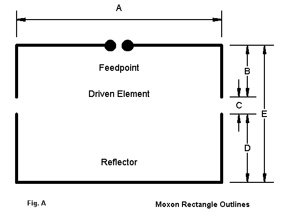
Figure A provides an outline sketch of a basic Moxon, a refresher. As well, the portions of the Moxon structure are identified, since we shall once more provide some design ideas involving this antenna. However, this month, we shall include 30 meters.
A 30-meter Yagi with unloaded elements would be about 48′ to 49′ side-to-side. A Moxon rectangle for 30 meters requires only 35′ of side-to-side space, and about 13′ front-to- back. These dimensions are close to those for a common 20-meter beam. The structure of a 30-meter Moxon might have to be a bit beefier than that of a 20-meter Yagi, since the parallel element must support the “tails” (B and D in Figure A). Nonetheless, for those with space limitations, 35′ elements are usually easier to sustain than 48′ elements.
A 30-17 m Combination
When we examined the possibilities for 17 and 12 meters, we reached two practical conclusions. First, a dual Moxon array may be too sensitive to minor variations to be truly practical for home building. Second, placing a full size 12-meter Yagi of driver- reflector design inside the 17-meter Moxon was not feasible due to the length of the 12- meter elements–especially the reflector.
Therefore, we shall bypass a dual Moxon for 30 and 17 meters. However, we shall not forego the possibility of a full-size 17-meter Yagi placed within the frame of a 30-meter Moxon. The longest element of a driver-reflector Yagi for 17 meters is 27′ and that should be no problem within the 35′ dimension of the 30-meter Moxon. Figure 1 shows the general outline of the combination.
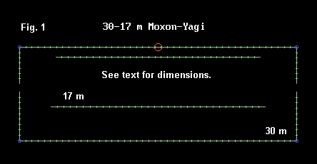
The following table of dimensions uses the designators of Figure A for the Moxon. The Yagi element spacing entries are distances from the Moxon driver. All dimensions are in feet. The Moxon elements are 1.25″ aluminum tubing, while the Yagi elements are 1″ diameter aluminum tubing.
| Band | Dimension (all elements use 1.25″ diameter aluminum tubing) | Length (feet) |
|---|---|---|
| 30-meter Moxon | A | 34.91′ |
| B | 4.89′ | |
| C | 1.12′ | |
| D | 6.56′ | |
| E | 12.57′ | |
| 17-meter Yagi | (all elements use 1.0″ diameter aluminum tubing) | |
| Driver | Length | 25.80′ |
| Space | 1.30′ | |
| Reflector | Length | 27.00′ |
| Space | 8.00′ |
The spacing between the Yagi elements is 6.7′ or about 1/8 wavelength. The spacing of the Moxon elements is about 0.13 wavelength. The Moxon dimensions are unchanged from those optimized for maximum front-to-back and a 50-Ohm feed when used independently. Of course, changes in material dimensions or the use of stepped-diameter elements will require readjustment of the design to yield satisfactory performance. As I did last month, I shall place model descriptions at the end of these notes for those who wish to experiment with other material combinations.
However, once the basics are established, the only post-construction adjustment will be to the slaved 17-meter driver. Its exact length and spacing from the Moxon driver will determine the feedpoint impedance on 17 meters at the physical feedpoint.
The Moxon-Yagi combination is a very well-behaved. The following performance table, listing the gain in terms of free-space gain, gives a good general picture.
| Frequency (MHz) | Gain (dBi) | Front-to-Back Ratio (dB) | Feedpoint Z (R+/-jX Ohms) | 50-Ohm VSWR |
|---|---|---|---|---|
| 10.100 | 6.21 | 22.9 | 47.6 – j 3.6 | 1.09 |
| 10.125 | 6.13 | 27.0 | 50.7 – j 1.4 | 1.03 |
| 10.150 | 6.05 | 33.4 | 53.7 + j 0.6 | 1.07 |
| 18.068 | 6.37 | 10.8 | 52.4 – j22.5 | 1.55 |
| 18.118 | 6.26 | 10.9 | 49.9 – j 5.4 | 1.11 |
| 18.168 | 6.16 | 10.9 | 47.5 + j10.9 | 1.26 |
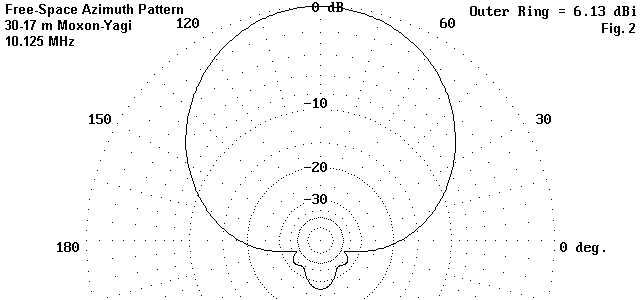
As we saw last month, the addition of a closely-spaced parasitic beam slightly detunes the Moxon in terms of moving the peak front-to-back ratio upward in frequency. However, the gain and the source impedance are mostly unaffected. Figure 2 provides a free-space azimuth pattern of the 30-meter Moxon performance at mid-band. One of the side-benefits of the Moxon rectangle design is that it tends to hold its high front-to-back ratio even down to a height of 3/8 wavelength–about 36′ on 30 meters. Of course, the old rule that higher is better still applies. Nevertheless, even a modest installation can expect quite reasonable results on 30 meters.
On 17 meters, we must expect the lesser front-to-back ratio associated with the driver- reflector Yagi design. Figure 3 shows the mid-band free-space azimuth pattern for the array at 18.118 MHz.
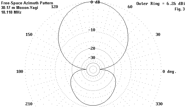
Because the upper band Yagi is behind and within the Moxon rectangle, there is no significant forward-stagger effect. Hence, the Yagi gain and front-to-back ratios are virtually identical to those one might obtain from an independent driver-reflector Yagi for 17 meters. However, with 1/8 wavelength spacing, the feedpoint impedance of an independent Yagi would be closer to 35 Ohms. The near-50-Ohm match is obtained by virtue of the open-sleeve coupling, which can be set for virtually any desired impedance by changes in the length and/or spacing of the driver relative to the physically fed element. As we saw last month, the impedance changes more rapidly on a slaved element than on a directly fed element. In the case of the 17-meter Yagi, it is the reactance that undergoes the most rapid change, while the resistance remain quite stable.
Although the 17-meter Yagi does not gain anything from being inside the Moxon, it does not lose anything either. Moreover, it does not take up an additional space on a supporting tower. The two-band array has identically the same outside dimensions as the 30-meter Moxon itself. Except for the additional weight and wind load of the 17-meter elements, there seems little reason not to add the upper band if one seriously plans a 30-meter Moxon.
A 30-17-12 m Combination
Suppose we might be willing to extend the boom of the Moxon-Yagi from 12.6′ to about 16 feet. For the additional 3.4′ of boom length, we add one more band to the array–with virtually no change in the design work done so far. A driver-director Yagi with an element spacing of about 0.07 wavelength can be added ahead of the Moxon driver to arrive at a WARC 3-band array of considerable compactness. Figure 4 shows the general outline of the arrangement.
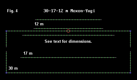
For the lower bands, the design once more uses 1.25″ diameter elements for 30 and 1″ diameter elements for 17. The 12-meter elements are 0.5″ in diameter, and everything is aluminum. With these materials we can uses the dimensions in the table below. For the 17-meter elements, the spacing entry indicates the distance behind the Moxon driver. For 12 meters, the spacing entry indicates the element spacing forward from the Moxon driver.
| Band | Dimension (all elements use 1.25″ diameter aluminum tubing) | Length (feet) |
|---|---|---|
| 30-meter Moxon | A | 34.91′ |
| B | 4.89′ | |
| C | 1.12′ | |
| D | 6.56′ | |
| E | 12.57′ | |
| 17-meter Yagi | (all elements use 1.0″ diameter aluminum tubing) | |
| Driver | Length | 25.80′ |
| Space | 1.30′ | |
| Reflector | Length | 27.00′ |
| Space | 8.00′ | |
| 12-meter Yagi | (all elements use 0.5″ diameter aluminum tubing) | |
| Driver | Length | 19.46′ |
| Space | 0.70′ | |
| Director | Length | 18.70′ |
| Space | 3.43′ |
For the Moxon and the 17-meter Yagi, nothing has changed. The dimensions of the 12-meter Yagi are very slightly different from those used with the 17-meter Moxon last month. However, that Moxon used elements with a smaller diameter than the 30-meter Moxon in this design. The major change is in the spacing from the Moxon to the 12-meter slaved driver–somewhat wider than in the 12-17 design.
If we see little difference in dimensions, we should also expect little difference in performance. The following performance table provides the numbers.
| Frequency (MHz) | Gain (dBi) | Front-to-Back Ratio (dB) | Feedpoint Z (R+/-jX Ohms) | 50-Ohm VSWR |
|---|---|---|---|---|
| 10.100 | 6.23 | 22.5 | 48.5 – j 4.9 | 1.11 |
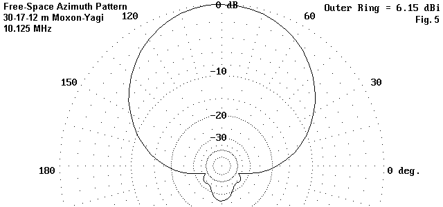
| 10.125 | 6.15 | 26.3 | 51.7 – j 2.8 | 1.07 |
| 10.150 | 6.07 | 32.1 | 54.9 + j 0.9 | 1.10 |
| 18.068 | 6.40 | 11.3 | 53.3 – j16.3 | 1.38 |
| 18.118 | 6.31 | 11.4 | 51.3 – j 1.2 | 1.04 |
| 18.168 | 6.21 | 11.4 | 49.4 + j13.6 | 1.31 |
| 24.89 | 6.57 | 25.3 | 59.4 – j 9.9 | 1.28 |
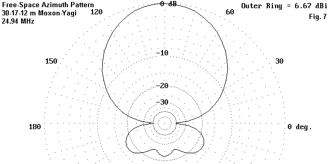
| 24.94 | 6.67 | 22.1 | 48.7 + j 3.4 | 1.08 |
| 24.99 | 6.76 | 19.2 | 38.9 + j18.5 | 1.62 |
On 30 meters, performance only shows insignificant changes in the last decimal places of the performance figures. On 17 meters, the performance values are numerically up, but again, not in a way that makes a difference that one could detect in use. The numeric increase is due in part to the forward stagger effect that gives the 12-meter elements a slight director effect during 17-meter operation.
On 12 meters, the 2-element driver-director array performs normally for an antenna of this type, although the independent feedpoint impedance of about 20 Ohms is overcome by slaving the driver to the 30-meter Moxon driver. Last month we saw higher gains on 12 meters. However, the 30-meter driver is farther removed from the 12-meter elements and provides some isolation of them from the interior 17-meter elements. Hence, forward stagger effects are minimal.
Nonetheless, for a beam with a 16′ boom length, the tri-band Moxon-Yagi offers excellent potential. Figure 5 shows the free-space azimuth pattern at 10.125 MHz.
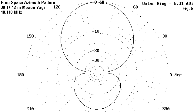
In Figure 6, we see essentially the same pattern as in Figure 3 for the middle of 17 meters. The 12-meter free-space azimuth pattern for 24.94 MHz (Figure 7) is similar to the one shown for 12 meters last month. The same rear quartering lobes are present to moderate the 180-degree front-to-back ratio.
The exact spacing and length of the slaved drivers will require field adjustment to arrive at a final setting to achieve a good 50-Ohm match on each band. However, those adjustments are about the only critical matters related to construction–once you decide on and design for the precise set of materials you will use. Essentially, you can design an independent Moxon for 30 meters and adjust it to perfection. Then, you can add the 17-meter elements and perform driver adjustments until you are satisfied. Rechecking the 30-meter impedance should show no significant change. Finally, add the 12-meter elements and adjust its driver for a good match on that band. Because element spacing is a bit more critical for driver-director arrays than for driver-reflector Yagis, recheck the element spacing for 12 meters before concluding the adjustment procedure. Once more, the impedances for 30 meters and 12 meters should not have significantly changed by adding the 12-meter elements.
I have good luck in adjusting Moxons and simple Yagis close to the ground by pointing the array as close to straight up as possible, with the reflector anywhere from 4 to 12 feet off the ground. The adjustments have held true at heights from 20 to 35 feet up. This technique is not applicable for all beams, but it is worth a try for those who do not relish adjusting beam elements from the top of a tower.
For those who wish to do further design work on models of the two antennas, here are model descriptions that should ease wire coordinate entries for most NEC modeling software.
30-17 m Moxon-Yagi – Frequency = 10.125/18.118 MHz.
Wire Loss: Aluminum – Resistivity = 4E-08 ohm-m, Rel. Perm. = 1
Wires
| Wire | Connection | End 1 X (Feet) | End 1 Y (Feet) | End 1 Z (Feet) | Connection | End 2 X (Feet) | End 2 Y (Feet) | End 2 Z (Feet) | Diameter (inches) | Segments |
|---|---|---|---|---|---|---|---|---|---|---|
| 1 | -17.457 | -4.888 | 0.000 | W2E1 | -17.457 | 0.000 | 0.000 | 1.25E+00 | 7 | |
| 2 | W1E2 | -17.457 | 0.000 | 0.000 | W3E1 | 17.457 | 0.000 | 0.000 | 1.25E+00 | 45 |
| 3 | W2E2 | 17.457 | 0.000 | 0.000 | 17.457 | -4.888 | 0.000 | 1.25E+00 | 7 | |
| 4 | -17.457 | -6.005 | 0.000 | W5E1 | -17.457 | -12.569 | 0.000 | 1.25E+00 | 9 | |
| 5 | W4E2 | -17.457 | -12.569 | 0.000 | W6E1 | 17.457 | -12.569 | 0.000 | 1.25E+00 | 45 |
| 6 | W5E2 | 17.457 | -12.569 | 0.000 | 17.457 | -6.005 | 0.000 | 1.25E+00 | 9 | |
| 7 | -12.900 | -1.300 | 0.000 | 12.900 | -1.300 | 0.000 | 1.00E+00 | 33 | ||
| 8 | -13.500 | -8.000 | 0.000 | 13.500 | -8.000 | 0.000 | 1.00E+00 | 33 |
Sources
| Source | Wire Segments | Wire # | Pct Actual | From End 1 | Specified | Ampl.(V, A) | Phase (Degrees) | Type |
|---|---|---|---|---|---|---|---|---|
| 1 | 23 | 2 | 50.00 | 2 | 50.00 | 1.000 | 0.000 | V |
Ground type is Free Space
30-17-12 m Moxon-Yagi Frequency = 10.125/18.118/24.94 MHz.
Wire Loss: Aluminum — Resistivity = 4E-08 ohm-m, Rel. Perm. = 1
Wires
| Wire | Connection | End 1 X (Feet) | End 1 Y (Feet) | End 1 Z (Feet) | Connection | End 2 X (Feet) | End 2 Y (Feet) | End 2 Z (Feet) | Diameter (inches) | Segments |
|---|---|---|---|---|---|---|---|---|---|---|
| 1 | -17.457 | -4.888 | 0.000 | W2E1 | -17.457 | 0.000 | 0.000 | 1.25E+00 | 7 | |
| 2 | W1E2 | -17.457 | 0.000 | 0.000 | W3E1 | 17.457 | 0.000 | 0.000 | 1.25E+00 | 45 |
| 3 | W2E2 | 17.457 | 0.000 | 0.000 | 17.457 | -4.888 | 0.000 | 1.25E+00 | 7 | |
| 4 | -17.457 | -6.005 | 0.000 | W5E1 | -17.457 | -12.569 | 0.000 | 1.25E+00 | 9 | |
| 5 | W4E2 | -17.457 | -12.569 | 0.000 | W6E1 | 17.457 | -12.569 | 0.000 | 1.25E+00 | 45 |
| 6 | W5E2 | 17.457 | -12.569 | 0.000 | 17.457 | -6.005 | 0.000 | 1.25E+00 | 9 | |
| 7 | -12.900 | -1.300 | 0.000 | 12.900 | -1.300 | 0.000 | 1.00E+00 | 33 | ||
| 8 | -13.500 | -8.000 | 0.000 | 13.500 | -8.000 | 0.000 | 1.00E+00 | 33 | ||
| 9 | -9.730 | 0.700 | 0.000 | 9.730 | 0.700 | 0.000 | 5.00E-01 | 25 | ||
| 10 | -9.350 | 3.430 | 0.000 | 9.350 | 3.430 | 0.000 | 5.00E-01 | 25 |
Sources
| Source | Wire Segments | Wire # | Pct Actual | From End 1 | Specified | Ampl.(V, A) | Phase (Degrees) | Type |
|---|---|---|---|---|---|---|---|---|
| 1 | 23 | 2 | 50.00 | 2 | 50.00 | 1.000 | 0.000 | V |
Ground type is Free Space
The 30-17 or the 30-17-12 combination arrays offer some interesting potentials for small WARC band beams. These design notes aim to whet your appetite for further and improved designs. However, you will have to go some to improve performance on all bands while shrinking the size of these arrays. However, if you do manage the trick, I’d be first in line to find out how.
Originally posted on the AntennaX Online Magazine by L. B. Cebik, W4RNL
Last Updated : 4th June 2024
