The Ground Plane - A Simple but Good Antenna
Since then, I have had a number of verticals, including several phased arrays capable of punching a hole in the SWBC stations that inhabit 40 meters at night. This array was the one HY Gain had published in a small free publication found in most ham stores. It was made up of ¼ wave ground planes spaced ½ wavelength apart and fed with phasing lines.
So the simple ground plane is a good cheap and simple antenna anyone can put up. For the higher bands, it is an easy manner to make the antenna of small diameter tubing and place it on the roof. The construction of a ground plane for the lower bands must be made of more substantial material. One ham made a top-loaded vertical for 160 meters using 3-inch (7.62 cm) tubing, and sheet metal screws as fasteners to hold the tubing together. It was 90 ft.(27.36 meters) tall with a coil located at the top section with a 1.5-inch (3.81 cm.), 10 ft long (3.04 M.) top whip. Also, there was a matching coil at the bottom of the antenna.
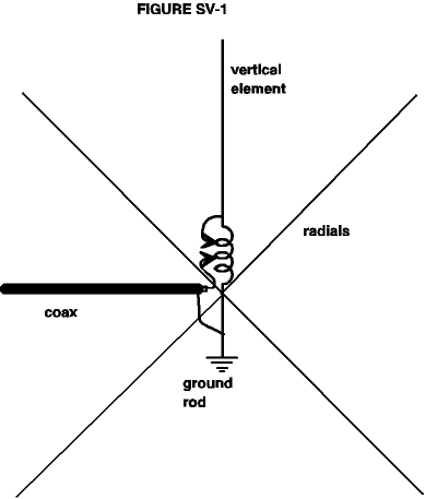
The big complaint folks have about the ground plane is that it requires radials. This is not too difficult to manage, as they do not have to be in a straight line, but can be strung out in any direction to make them fit. Just be sure the radials will not be where they will trip anyone, or snag anyone anywhere else. Figure 1 illustrates the basic antenna and also shows a coil used for matching to the feedline as well as fine-tuning the antenna to resonance, if your radiator is a little short.

Another thing this coil does is provide a path to ground for static electricity. The other complaint is the vertical antenna is more prone to pick up noise than a horizontally polarized antenna. This is true however, a ground plane has a much lower angle of radiation than a dipole. The vertical angle is around 25-29 degrees, which is good for DX chasing.
Here is the formula for figuring out the correct length for the vertical radiator. It is rather simple and you can also use the same length for the radials:
234/F=L, where F= frequency and L= length
That is all that there is to it. Use a good ground at the base of the antenna for static drain purposes and another ground to supplement your existing ground. Also, you can make the top of the antenna come to a point or bunch of points to drain off static electricity. There is a device on the market designed to be put on top of an antenna or tower. It looks like a porcupine, hedgehog or pincushion and is designed to allow the bleeding of static electricity into the air. This is designed to help prevent lightning strikes. Figure SV-1 above shows the basic design of a ground plane.
Now for some interesting notes. If you connect the ends of each radial to each to form a square, there is some evidence this will lower the angle of radiation somewhat. Not much, but every little bit helps. Another interesting fact is that apparently shorter radials will also help the overall efficiency of the antenna. If you use shorter radials, use at least 1/8 wavelength long radials and as many as you can put out. Then tie the far ends together with a long piece of wire. This will help your signal some by improving overall antenna efficiency a little more. Figure 2 shows how this can be done.

This is a top view and the antenna is in the center. Again, the radials should be put where they can be made to fit which may not be as perfectly as illustrated. The simple ground plane may be the only antenna to best fit in some locations and if installed correctly will work well.
There are several variations which can be constructed using the simple ground plane. One is to phase a pair of these antennas for either ½ wave spacing which will give a choice of directions, either directly perpendicular to the antenna or in line with the antennas. This is accomplished by either phasing the antennas 180 degrees out with respect to each other or in phase with each other.
Another variation is to space two antennas ¼ wavelength apart and feed them 90 degrees out of phase with respect to each other. This is done by inserting a ¼ wavelength of coax to give the required phase shift. Also, if you elevate the antenna somewhat, the losses caused by the ground will be lowered.
Now, bear this in mind as well. You will not operate efficiently with local contacts out to 1000-1,200 miles (1609-1931 km) as this antenna does not have any high angle radiation to give local coverage. If you want local coverage, you will have to switch to another antenna. Folks will hear you, but anyone with a dipole will be stronger. This applies to the lower bands, 160, 75 and,40 meters. There is not enough ground wave on the higher frequencies to cover much more than a few miles or kilometers out from your shack.
Originally posted on the AntennaX Online Magazine by L.B. Cebik, W4RNL
Last Updated : 15th March 2024
