Lightning Resistant Antenna
The “Folded” 1/4-wave lightning resistant element makes a wonderful omi-directional bas station for use from 6 meters to 440 MHz. Due to the low length-to-diameter ratio, good bandwidth can be expected over 6 meters, 220 or 440 MHz.
Plumbers Dream
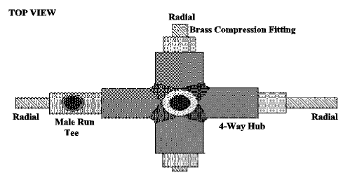
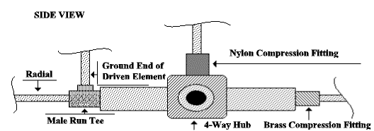
It is a plumber’s “dream”, constructed of fittings and tubing with limited tools. The vertical element is folded back to ground through a “male run tee” to the 4-way hub providing an excellent conduction path for lightning currents, protecting sensitive equipment, not to mention, you. To complete the ground path, the 4-way hub and mast should be connected to a heavy copper conductor (at least #2 AWG) which runs in the most direct route (outside the building) to a long grounding rod.


Matching
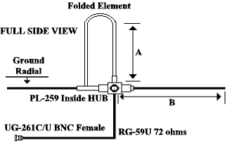
A single element 1/4-wave radiator (with perpendicular ground radials) has a character impedance of 35 ohms, but when a second element is closely coupled (as in the folded case), then the impedance is raised by four to 140 ohms. To match this antenna to 50-ohm coax, a 1/4-wave section of 72-ohm coax is utilized as an unbalanced matching device to ensure harmony between the antenna and your transmitter.
A PL-259 connector (less barrel) is used on the antenna end of the RG-59, with female insert from a SO-239 pressed into the element, arranged so they connect when the element is inserted into the nylon compression fitting. The feedline and matching section should be located in the tubular mast for weather protection. The bottom of the hub is threaded (1/2″ pipe) to accommodate a brass flair-to-pipe fitting which holds the PL-259 in place, as well as providing a 3/4″ pipe thread for the mast.
The ground radials are all connected to the hub via brass compression-to-pipe fittings. The feed point of the element is mounted by a nylon compression-to-pipe fitting, providing support and insulation. These compression fittings provide excellent environmental protection since they are intended for hydraulic use.

Details
The 1/4-wave matching line (RG-59) has been sucessfully operated at 45 watts and should easily handle 100, probably even 200 watts. Remember, RG-59 foam has a velocity factor of 79% and RG-59 is 66%. To ensure proper operation of the matching section, connect the test specimen to an SO-239 that has four 560-ohm resistors (short leads) in parallel to ground. This presents a 140 resistive load for length adjustments of the matching section via VSWR meter. VSWR values of less than 1.1 to 1 should be achievable.
The radiating element (dimension A) should be cut to 95% of a 1/4-wavelength (center of the band) and the four ground radials should extend 105% of a 1/4-wavelength from the hub center (even the radial with the male run tee). Target values and dimensions are:
| 6 meter | 2 meter | 220 MHz | |
|---|---|---|---|
| Diameter A | 54″ | 19.25″ | 12.25″ |
| Diameter B | 57″ | 20.25″ | 12.89″ |
| RG-59 Foam | 49″ | 17.50″ | 11.15″ |
| Tubing Diameter | 3/8″ | 1/4″ | 1/4″ |
| Nylon C/F | 289-N-06×06 | 284-N-04×04 | 284-N-04×04 |
| 3 Brass C/F | 68-CM-06×06 | 68-CM-04×04 | 68-CM-04×04 |
| Male Run Tee | 71-CM-06×06 | 71-CM-04×04 | 71-CM-04×04 |
It would be advisable to cut all of the elements slightly long and assemble the antenna to perform VSWR measurements. Longer elements should produce a better VSWR at the low frequency end of the band and worse VSWR at the upper end. Then trim and test shorter element lengths to achieve balanced VSWR across the band. Final VSWR should be typically 1.2 to 1 across the band.
Seal Well
Sealer should be used on the open ends of the 4 ground radials to prevent moisture from entering the main hub assembly.
This design was originally constructed and tested in the 2 meter band with good results. Values were calculated for 6 meters and 220 MHz, however, I will wait until more work is accomplished before predicting 440 MHz dimensions or performance.
Originally posted on the AntennaX Online Magazine by David L. Stanislaw, N0JWY
Last Updated : 12th March 2024

