
Antenna Bridges
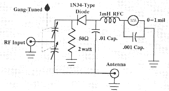
Of course we are talking about a simple RF bridge which has been presented in various magazines and handbooks. A simple version of one has been in the ARRL Handbook for some time. The one shown for this article has provisions for measuring reactance also, but that can be omitted if desired. I chose to build the bridge using tuning capacitors for the bridge balancing control. I am sure the bridge using the resistance method of balancing the bridge works very well too. However, I think the bridge with the capacitors for balancing is easier.
Several Versions Out There
There are several versions of the bridge circuit although they are all similar. The one I used I cannot remember where it came from as the bridge was built probably thirty or so years ago. The caps for the bridge are two 140 pF condensers ganged together with one section180 degrees different form the other. One condenser is fully mesh, the other open. This was the cheap way of getting a differential dual condenser. The two 140 pF condensers were from BC Electronics for a dollar each, and to add insult to injury, they were silver-plated! The shafts projected from the back of the condensers for 1/4 inch, making it easy to gang two of them.
At the same time I obtained several 150 pF transmitting condensers, by Johnson, with 3000 volt spacing for $1.50 each. Two of these condensers were ganged together in my antenna tuner for many years. These types of bargains are hard to come by today. Flea markets still have small condensers with many long shafts for ganging. The capacity is not that important since most of the loads we work with are 100 ohms or less. Probably anything from 80-200 pF will do. The remainder of the parts can be found at your Electronics Supplier.
Null Indicator
The meter I used for the null indicator was a surplus item intended for a small cassette recorder. Full scale reading of one mil without any scale calibration except low and high. This works very well because we run just enough power to get a full scale reading and then tune for a null. I still see these small 0-1 mil meters, intended for cassette recorders, in the surplus ads at low prices. Their small size makes them ideal for small equipment boxes. If you have a VOM with a 1 or 5 mil range, it could work as a plug-in meter.
Reactance
I never built a reactance measuring network, as for most amateur work, I didn’t think it was necessary. To drive the bridge, we use the station transceiver. I run just enough output to give a full scale reading on the null meter. Be sure the bridge is not tuned to a null when you start because it is possible to damage the bridge with excessive power input.
When a deep null is obtained, it usually means there is little reactance. If the null is shallow it usually means there is large reactance along with the resistance. I have used a GR 1606A RF bridge (bought at the Dallas sidewalk sale for only $245) along with the signal generator and null detector, which in this case was a Hallicrafters S20R.
The amount of time it takes to carry this equipment out to an antenna, set it up, find a 120V ac source, etc., just seemed like too much trouble for most casual measurements. By using the station transceiver for the RF source, only the bridge is needed at the antenna. If the antenna is high in the air, a half wavelength of coax or multiples of a half wave will repeat the impedance found at the antenna. Of course you don’t get 1/2 ohm accuracy on both resistance and reactance, but we are not interested in that kind of measurements in amateur work.
Use a Resistor
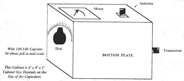
One last word on building the bridge. Use at least a two-watt resistor for R1 since, at times, we run a little power into the bridge. If a two-watt carbon resistor is not available, try paralleling several 1/2 watt ones to reach the two-watt rating. Four 220-ohm 1/2 watt carbon resistors will work. I had found a number of two-watt 5% resistors at a hamfest in Oklahoma City a number of years ago. They were fifty ohms, but anything from 47-55 should do. Just find some 2% or 5% resistors at Radio Shack to calibrate the bridge. A piece of light cardboard was glued to the front of the bridge and calibrated in ink. After calibration we covered the dial with clear fingernail polish. Even today, after many years, the dial is usable and easy to read. The bridge can be housed in anything that is at hand. Mine is in a small chassis with a bottom plate.
You Can Do It
For any serious work with antennas, the antenna bridge is a must. Half the fun of working with amateur radio is to build your own test gear. If you cannot find any suitable capacitors, then build one of the resistance bridges. With the addition of a simple RF bridge, antenna work can be fun!
Originally posted on the AntennaX Online Magazine by Glenn Thomas, W5INU
Last Updated : 17th March 2024