Your Antenna and its Surroundings - How They Interact
For the purposes of this discussion, the antennas being used are an inverted V and a vertical, both for 40 meters, but used separately. Only one will be up at a time and this will simplify things a great deal. Both antennas are in use all over the world, and in many places, the vertical is the only antenna that can be used due to space and sometimes concealment advantages that only a vertical has.
Now, for the first antenna, this is the situation. J. Bacon Hambone just got his license and wants to work 40 meters. He lives on a lot that is 120×60 ft. It is a new subdivision and there are no trees to mount an antenna. So, he manages to put up a 35-ft. high mast made of 2×4 studs and the ends are located on shorter 2×4 studs and are 20 feet high. By careful alignment he manages to get the antenna up between the power lines and telephone drop to his house. After running the coax into the house, J. Bacon gets the antenna loaded up and gets on the air. The SWR is fine and all is well. Well, maybe.
The antenna is literally surrounded by conductors of electricity and so is the rf the antenna is radiating. So what happens to all that energy being radiated into the power lines and the telephone drop? How does it interact with the antenna?
If you look at Figure 1, this is the normal current distribution of current in a dipole antenna being used as an inverted V.
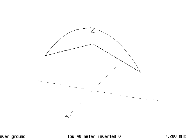
Figure 2 is the horizontal pattern and it is rather oval in shape.
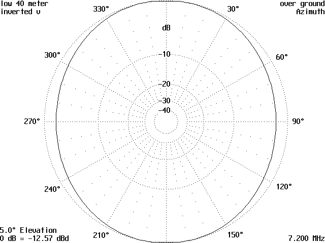
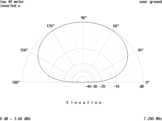
Figure 3 is the vertical radiation pattern and it is also a more nearly circular pattern. The 3D pattern is omitted as it resembled a short fat hot dog bun. These patterns are of an antenna with no other surrounding conductors in the immediate near field. This is what should result from this antenna under these conditions.
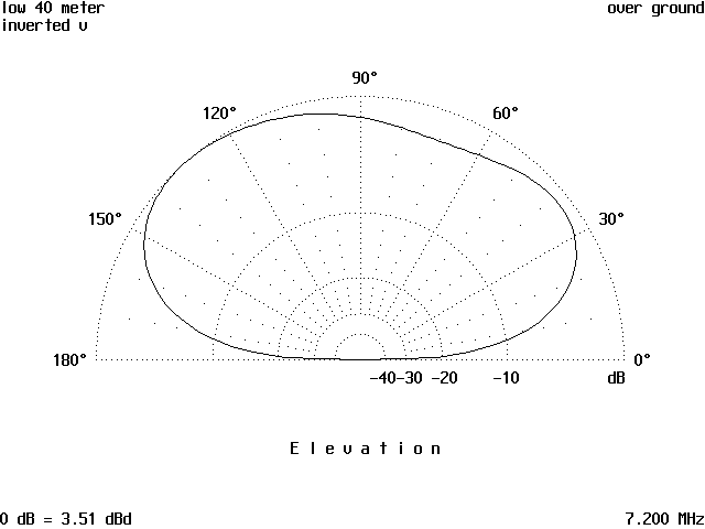
Now look at Figure 4. This is the vertical radiation pattern of the same antenna, only it is affected by telephone cables, power line drops and a telephone drop to J. Bacon’s house, all of which absorb and re-radiate the energy that comes from his inverted V antenna.
The antenna in Figure 5 is surrounded by similar hazards. The two vertical lines are ground wires present on all power poles. They also pick up and re-radiate rf into the air. The small sloping line is the telephone drop, made from mid-span with a clamp on the strand. It also re-radiates the rf energy. The heavy line is the 220 drop to the house. It consists of 2 hot wires and one neutral, which also contribute to the absorption and re-radiation. The one line that runs from lower left of the figure to the upper right is the telephone cable and steel strand it is strapped to. The line running from lower right to upper left is from the power lines, all three of them.
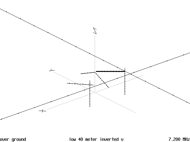
All of these conductors are both absorbing and re-radiating the energy from the inverted V, which is in the middle, and the end result is the horizontal pattern in Figure 6 and the vertical pattern in Figure 7.
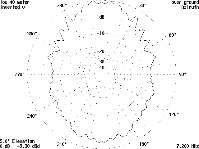
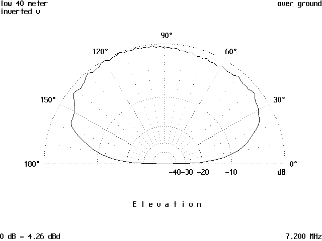
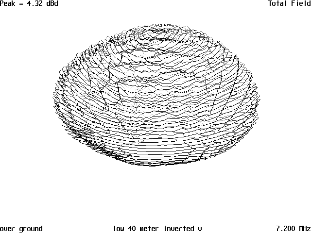
The result is the 3D pattern in Figure 8, which resembles some marine creature that might be found on a reef somewhere, many stubby spikes and wrinkles in the pattern. It looks like something you would not want to step on. All of which causes the pattern to radiate in strange ways and directions. This is a result of not only current re-radiating from the different conductors, but also due to the phase shifting that also takes place. The out of phase radiation can cause cancellation of the signal in certain directions and addition in others. In this case, the power line was figured in the calculations for a total of 2,000 feet with the antenna located in the center. The telephone cable also was calculated for a total of 2,000 feet.
The resultant currents are shown in Figure 9, and the phases were not figured in for this example. As you can see the currents induced into the telephone cable and the carrier strand are of rather large magnitude which tend to propagate along the cable. The power lines have about half of the current as the power line but of significant magnitude. The large loop at the center of the pattern is the rf current induced into the telephone drop line going into the house. There it will cause interference with conversations and probably allow the telephone user to get rf burns on the lips or ears, depending on how much power was being run.
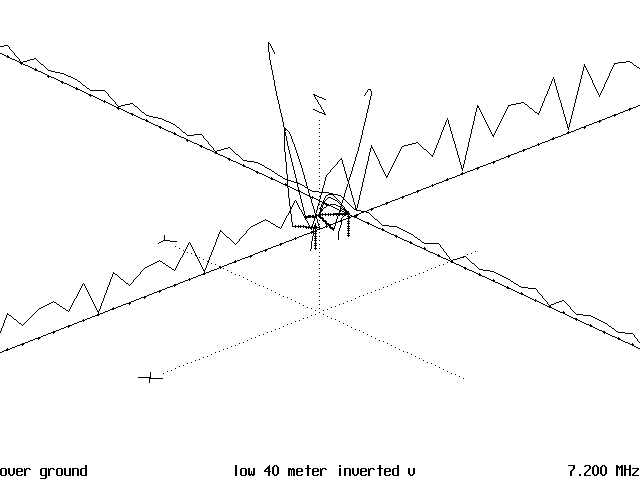
The two large lines with small hooks at the top of them are the currents in the antenna proper. The very small loop just visible over the power drop, which is the last L-shaped dark lines, is the current in the power drop. Now, a very real problem is that these induced currents can cause tvi in sets some distance away from your location, due to the power lines carrying the rf into the TV set. Same thing occurs with any other device like a radio or VCR. The telephone is the next victim, but in most places the local phone companies have bypass capacitors easily installed if needed or in some cases, are already installed to prevent a problem from occurring.
So, now it can been seen there is a considerable amount of current that can be induced in the surrounding conductors with a definite affect on what the shape of radiated pattern. By comparing the patterns of the non-surrounded antenna with the surrounded antenna, this can easily be seen. Keep in mind that this was only done on one frequency range, 7.2.00 MHz. What the results on other frequency ranges are up for another calculation.
Next, J. Bacon wants to put up a vertical on 40 meters because he heard the 1/4 wave vertical is a good DX antenna. Up goes a vertical with 4 1/4 wave radials which looks like Figure 10.

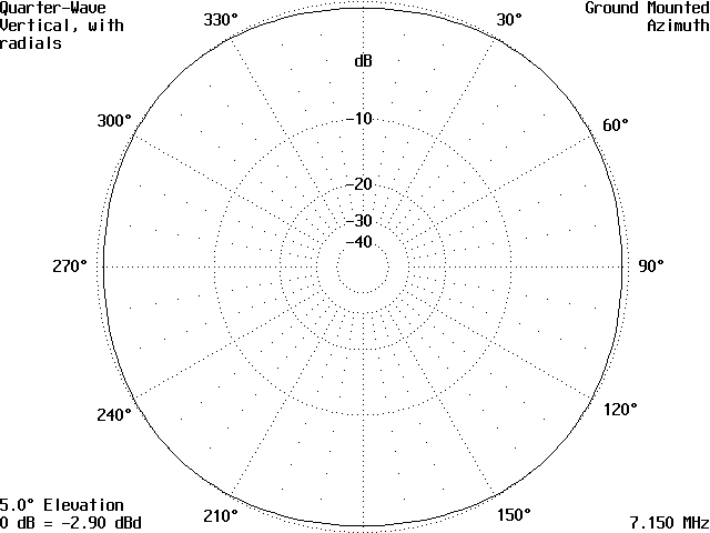
It has a horizontal pattern as shown in Figure 11 and a vertical pattern as shown in Figure 12.
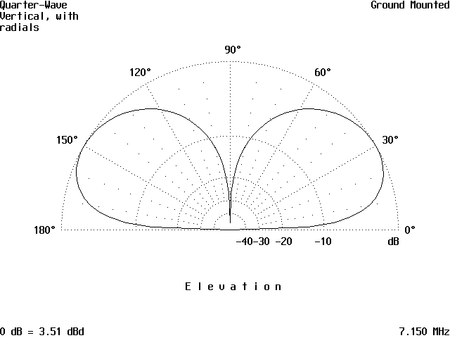
The angle of radiation is lower than the inverted V, being around 30-35 degrees, which is good enough for DX most of the time. Current distribution is shown in Figure 13 and shows only magnitude, not current phase.
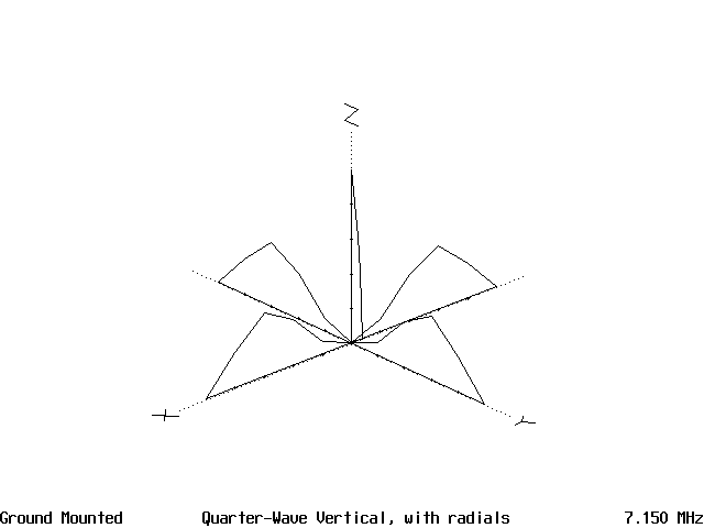
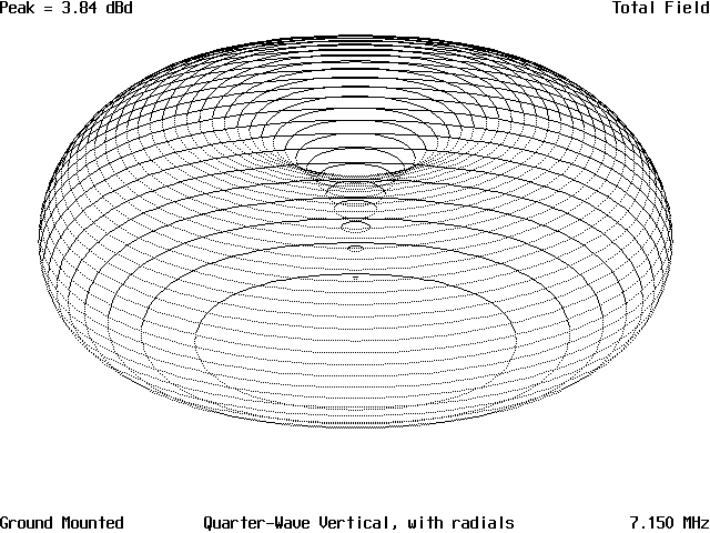
Figure 14 is the 3D pattern and shows the typical half-donut pattern of a vertical in the clear.
But this antenna is not in the clear, as shown by Figure 15. This is the same surroundings the inverted V had to deal with. So how does this effect the vertical?

Figure 16 shows the new horizontal pattern to have changed into a rounded square, however this is not going to be too noticeable in most cases. The vertical pattern is a different case.
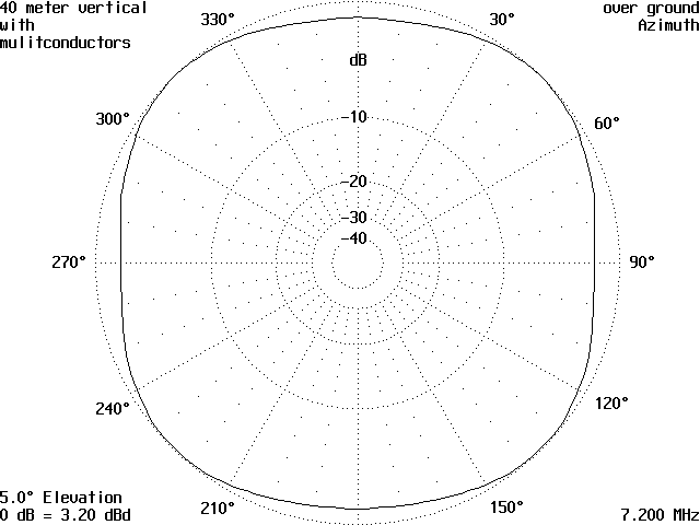
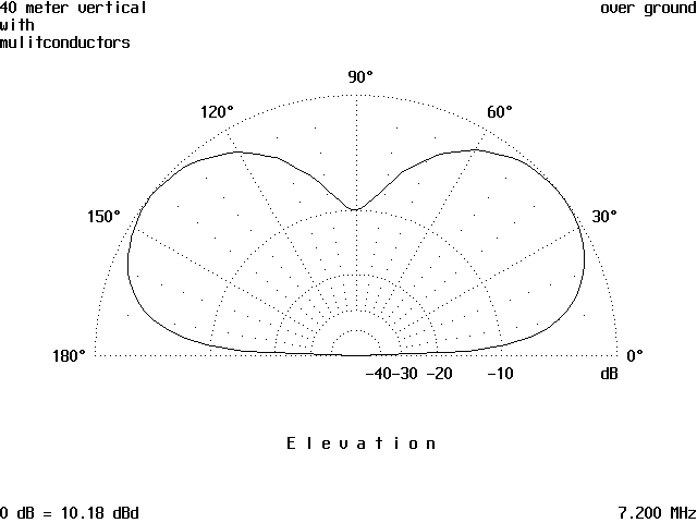
Figure 17 is the vertical radiation pattern and the angle of radiation has increased some to the range of 38-45 degrees. Not much, but still a change. In all probability there would not be too much noticeable affect on the signals incoming and outgoing.
But, if you look at the currents in Figure 18, there is a huge change in antenna and radial currents. Again, only magnitude not phase is shown. The currents in the radials has changed enormously, as did the currents in the surrounding conductors.
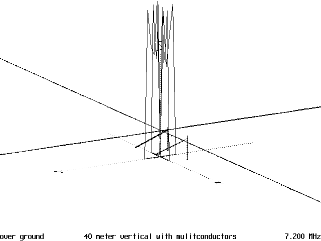
This is different due to the vertical ground conductors found on the power poles, which are close enough to the correct length to resonate on 40 meters, 33 feet. So, there is a huge amount of current induced in these conductors and this means a lot more rf to be re-radiated back into the air and cause phase cancellation or addition to the antenna radiation, depending on spacing and other surrounding conductors. What do the re-radiated currents look like with the phase figured in? Figure 19 shows the current amplitudes and phases. There is a tremendous interaction between the vertical antenna and radial system, with currents being 90 degrees out of phase in the system due to the phase-shifted current being re-radiated from the power and telephone drops back into the system. The one good thing is there is a very minimum of current being radiated into the power lines and telephone cables.

Figure 20 shows the pattern no longer has the deep null straight up that the vertical alone has, as well as a small crease to the upper left of the center of the pattern that extends across to the lower right through the center of the pattern.
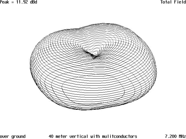
The only solution is to try to get the antenna as far as possible from the surrounding conductors and as high as possible. That may not be possible, due to the small lots some of us are forced to live on in a city. The country dwellers have far less problems with this than us less fortunate city folks.
We are not the only ones that have problems with surrounding objects causing a problem, so you may console your self with this last comment. A local broadcast station experienced a tremendous change in their nighttime pattern. After much testing of the phasor cabinet and cables to the 4-tower array, and every thing else they could test, someone noticed a 300-ft. communications tower had been erected about 1/3 mile away. It was determined the new tower had caused enough distortion of the nighttime pattern and the phasing cabinet at the transmitter could not compensate for the added phase shifted currents that were induced back into the broadcast antenna system. Alas, the phasor cabinet had to be redesigned at great expense which then brought about a lawsuit against the company who had put up the new 300-ft. tower.
The surrounding objects also can cause your received signals to be affected, and as you have seen sometimes for the good and sometimes for the bad. It is a throw of the dice. Just be glad that you don’t have to spend a bundle to correct your phasor cabinet problems.
Originally posted on the AntennaX Online Magazine by Richard Morrow, K5CNF
Last Updated : 16th March 2024
