Antenna Resistance
Any antenna has an impedance (Z), which is defined as Z=R+jX. For our purpose, the equivalent circuit of an antenna can be drawn as a simple series circuit (see Figure 1), composed of resistance, capacitance, and inductance. At this rime, I want to explain the resistance of an antenna. The other components will be covered in future articles.
There are two (2) types of resistance, good and bad. The good resistance is the Radiation resistance of the antenna. The bad resistance is the loss resistance. The resistance of the antenna can be measured using OHM’s law, which is R=E/I. That is to say that if we place a voltage across the antenna and measure the current, we can calculate the resistance. You can only do that if the reactance is zero, which means the antenna is resonant. For that special case, X=0, therefore Z=R+j0 = R.
Unfortunately, you can not measure radiation resistance and loss resistance separately. That says another method must be used to determine their values. The Radiation resistance can be calculated, then by measurement we can determine the total value of resistance. By subtracting the calculated radiation resistance from the total we can determine the loss resistance. The only reason we need to know the value of each one separately is to allow us to calculate the efficiency of the antenna. The efficiency of an antenna is the ratio of radiated power to the input power. In other words, part of the transmitter power will be converted to electromagnetic energy and radiate. Part of the transmitter power will be converted to heat due to the loss resistance.
Current flowing through the radiation resistance (RR) will radiate, and is therefore the output of the antenna. Current flowing through the sum of the radiation and loss resistance (RL) is the total input power. This can be expressed as follows:
Efficiency = RR/(RR + RL)
Most of you have not been concerned about the loss resistance of the antenna for two reasons. First, in a large antenna it is so small that it has very little effect on the efficiency. However, the main reason is that there is very little you can do about it in “conventional” antennas. To illustrate the effect, we will use a conventional mobile antenna on 75 meters as an example.
If we use a whip antenna eight (8) feet tall at 3.8 MHz over a perfect ground, the calculated value for RR is 0.357 ohms.(Sometime in the future I will tell you how to determine that value). If we install that same antenna on a car, add a center loading coil, and measure the impedance at resonance, you will find that the sum of RR + RL will be about 12 ohms. By simple arithmetic, RL has a value of almost 12 ohms. Plug those values into the equation for efficiency and you will find that the typical mobile antenna on 75 meters only has an efficiency of 3%. That also tells you that a 100 watt transmitter connected to that antenna will only radiate 3 watts. Now you understand the importance of loss resistance.
Why is the loss resistance so high for that antenna ? Part of it is due to the loss resistance in the loading coil, but a lot of it is due to the loss in the ground return for the antenna, which is the body of the car. Steel is a lousy conductor of RF current for two reasons. In addition to the high value of resistance per unit area, there is also a magnetic field loss. When a current flows in a conductor, a magnetic field is developed. When a ferrous material is in a magnetic field, eddy currents are developed which cause current to flow. Both currents cause heating in the car body. Aluminum would be a much better choice, with copper preferred.
To make matters worse, RF currents only flow on the surface of a conductor. For this reason it is commonly referred to as skin loss resistance. The actual depth is a function of frequency, and can be determined for a copper conductor as follows: D = 2.6/F^.5, where D is measured in inches and F^.5 is the square root of the frequency in MHz. For example, the skin depth is only 0.00047 inches at 30 MHz. That is why we do not need solid conductors for antenna elements. For very low frequency coils, a large number of small insulated wires may be used in parallel to increase the surface area, and therefore reduce the loss resistance. That type of wire is called Litz wire.
The value of radiation resistance of an antenna depends on the size of the antenna (relative to it’s frequency of operation), the shape of the antenna, and the proximity to other objects capable of reflecting RF energy. That is why the feed point resistance of a dipole varies with height above ground, and the feed point resistance of multi-element beams is low. These effects will be covered in detail in future articles.
To look at one example of changing the shape of an antenna to control the radiation resistance, consider the dipole. The radiation resistance will be a maximum when the wire is straight, for any given height. As the wire is bent the radiation resistance will decrease. The inverted V antenna is a classic example of this technique to achieve a 50 ohm match. I will bet most of you thought that antenna just happened because someone got lazy and only had a single support pole. The inverted V is an excellent antenna in many respects and is the subject of another complete article.
When an antenna is close to a reflector, its radiation resistance will be low compared to its free space value. To give one example of the use of this characteristic, consider the stacked VHF commercial antennas. They are composed of vertical folded dipole elements in a vertical stack fed with a phasing harness. If a dipole is spaced 0.07 wavelengths from a reflector, it’s radiation resistance will be 12.5 ohms. By using a folded dipole the impedance is multiplied by a factor of 4 to a value of 50 ohms. Take notice the next time you drive by one of these.
These are just a sample of the basics and their use to allow the design of an antenna for a specific purpose. All of these and many more will be explored in depth in future articles. We will also endeavor to add comments about basic comments as appropriate in the various antenneX articles
One Month Later - An Update.
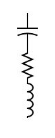
Any antenna has an impedance (Z), which is defined as Z=R+jX. For our purpose, the equivalent circuit of an antenna can be drawn as a simple series circuit (see Figure 1, Left) composed of resistance, capacitance, and inductance. In this article, I want to explain the resistance of an antenna. The other components will be covered in future articles.
There are two (2) types of resistance, good and bad. The good resistance is the Radiation resistance of the antenna. The bad resistance is the loss resistance. The resistance of the antenna can be measured using OHM’s law, which is R=E/I. That is to say that if we place a voltage across the antenna and measure the current, we can calculate the resistance. You can only do that if the reactance is zero, which means the antenna is resonant. For that special case, X=0, therefore Z=R+j0 = R.
Unfortunately, you can not measure radiation resistance and loss resistance separately. That says another method must be used to determine their values. The Radiation resistance can be calculated, then by measurement, we can determine the total value of resistance. By subtracting the calculated radiation resistance from the total, we can determine the loss resistance. The only reason we need to know the value of each one separately is to allow us to calculate the efficiency of the antenna. The efficiency of an antenna is the ratio of radiated power to the input power. In other words, part of the transmitter power will be converted to electromagnetic energy and radiate. Part of the transmitter power will be converted to heat due to the loss resistance.
Current flowing through the radiation resistance (RR) will radiate, and is therefore the output of the antenna. Current flowing through the sum of the radiation and loss resistance (RL) is the total input power. This can be expressed as follows:
Efficiency = RR/(RR + RL)
Most of you have not been concerned about the loss resistance of the antenna for two reasons. First, in a large antenna it is so small that it has very little effect on the efficiency. However, the main reason is that there is very little you can do about it in “conventional” antennas. To illustrate the effect, we will use a conventional mobile antenna on 75 meters as an example.
If we use a whip antenna eight (8) feet (2.4384m) tall at 3.8 MHz over a perfect ground, the calculated value for RR is 0.357 ohms.(Sometime in the future, I will tell you how to determine that value). If we install that same antenna on a car, add a center loading coil, and measure the impedance at resonance, you will find that the sum of RR + RL will be about 12 ohms. By simple arithmetic, RL has a value of almost 12 ohms. Plug those values into the equation for efficiency and you will find that the typical mobile antenna on 75 meters only has an efficiency of 3%. That also tells you that a 100 watt transmitter connected to that antenna will only radiate 3 watts. Now you understand the importance of loss resistance.
Why is the loss resistance so high for that antenna? Part of it is due to the loss resistance in the loading coil, but a lot of it is due to the loss in the ground return for the antenna, which is the body of the car. Steel is a lousy conductor of RF current for two reasons. In addition to the high value of resistance per unit area, there is also a magnetic field loss. When a current flows in a conductor, a magnetic field is developed. When a ferrous material is in a magnetic field, eddy currents are developed which cause current to flow. Both currents cause heating in the car body. Aluminum would be a much better choice, with copper preferred.
To make matters worse, RF currents only flow on the surface of a conductor. For this reason it is commonly referred to as skin loss resistance. The actual depth is a function of frequency, and can be determined for a copper conductor as follows: D = 2.6/F.5, where D is measured in inches and F^.5 is the square root of the frequency in MHz. For example, the skin depth is only 0.00047 inches (.01194mm) at 30 MHz. That is why we do not need solid conductors for antenna elements. For very low frequency coils, a large number of small insulated wires may be used in parallel to increase the surface area, and therefore reduce the loss resistance. That type of wire is called Litz wire.
The value of radiation resistance of an antenna depends on the size of the antenna (relative to its frequency of operation) the shape of the antenna, and the proximity to other objects capable of reflecting RF energy. That is why the feed point resistance of a dipole varies with height above ground, and the feed point resistance of multi-element beams is low. These effects will be covered in detail in future articles.
To look at one example of changing the shape of an antenna to control the radiation resistance, consider the dipole. The radiation resistance will be a maximum when the wire is straight, for any given height. As the wire is bent the radiation resistance will decrease. The inverted V antenna is a classic example of this technique to achieve a 50 ohm match. I will bet many of you thought that antenna just happened because someone got lazy and only had a single support pole. The inverted V is an excellent antenna in many respects and will be the subject of a complete article in the future.
When an antenna is close to a reflector, its radiation resistance will be low compared to its free space value. To give one example of the use of this characteristic, consider the stacked VHF commercial antennas. They are composed of vertical folded dipole elements in a vertical stack fed with a phasing harness. If a dipole is spaced 0.07 wavelengths from a reflector, its radiation resistance will be 12.5 ohms. By using a folded dipole the impedance is multiplied by a factor of 4 to a value of 50 ohms. Take notice the next time you drive by one of these.
These are just a sample of the basics and their use to allow the design of an antenna for a specific purpose. All of these and many more will be explored in depth in future articles. We will also endeavor to add comments about basic comments as appropriate in the various antenneX articles.
Originally posted on the AntennaX Online Magazine by Ted Hart, W5QJR
Last Updated : 19th March 2024