After evolving the design of the CFA into a Barrel Shaped CFA, which has the same radiation pattern as a Dipole, the next obvious step was to remove half the elements of the Barrel Shaped CFA and add a ground plane. Early versions of this configuration for HF had an E Plate (barrel) 20 cm (7.9 inches) in diameter, a D Plate having a diameter of 40 cm (15.8 inches) and a ground plane sheet having an area of 1 square meter (a square about 40 inches on a side). This CFA performed well on the HF bands, including 160 meters.
Following this work, Dr. Kabbary returned to Egypt and began experiments with a ground plane antenna for the AM broadcast industry. At first he used a small CFA and ran a kilowatt of transmitter power.
In 1990, Dr. Kabbary released data relative to his findings on a CFA having a height of 2 meters (6.5 feet) and a ground plane diameter of 4 meters (13 feet). He successfully operated this antenna at a frequency of 850 kHz using a transmitter power of 25 kW.
In 1991, Dr. Kabbary released measured performance data on a CFA having a height of 3.7 meters (12 feet) that was operating on a frequency of 1161 kHz at a power level of 60 Kilowatts. A photograph of that antenna introduced article III of this series. The dimensions of that antenna were as follows: E Plate (barrel) diameter = 2 meters (6.5 feet), barrel length = 2.5 meters (8 feet), height of barrel above the ground plane = 1.2 meters (3.9 feet), D plate diameter = 4 meters (13 feet) spaced 0.6 meters (2 feet) above a ground plane having an area of 10 square meters (1,285 square feet). That CFA equaled the performance of a quarter wavelength vertical antenna.
It seems Dr. Kabbary was never satisfied, even though he had seemingly achieved the impossible. His colleagues tell me that he is one of the most astute individuals they have ever met. That translates into an unquenchable desire to go further and learn more. The result of that search brings us to a report released in 1995. Dr. Kabbary made a radical change in the dimensions of the antenna, including what must be described as a funnel shaped top. This new CFA is shown in the cover photo of the report on the following pages. This physical configuration allowed the transmitter power to be reduced from 100,000 watts while using a 1/4-wave vertical to 30,000 watts using the CFA and achieve the desired performance.
I feel it is important to include the full report in this article to give a complete description of this extremely important development of antennas. In the previous articles we have said little about the bandwidth of the CFA (which is limited only by the phasing/matching circuit). The report presents a VSWR plot to portray the significant bandwidth—much more than a conventional 1/4-wave vertical.
Work continues on the development version of both the Ground Plane and Barrel Type CFA’s for Hams. Details will be provided in the next article.
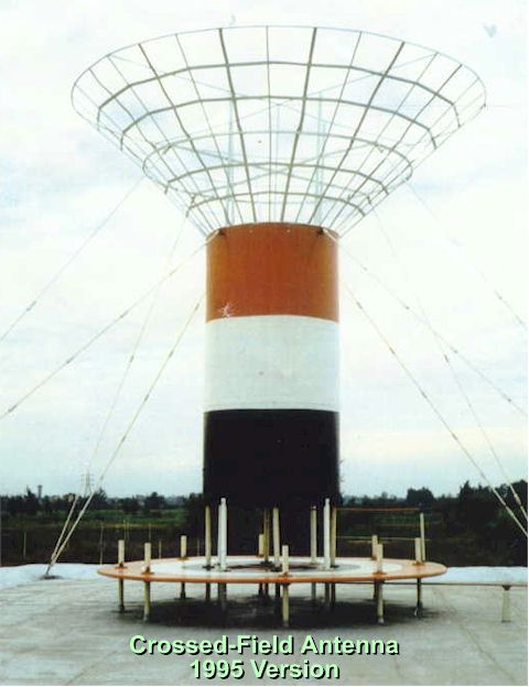
1995 Comparison Tests
Egyptian Radio and TV Union
From the Tanta Radio Station
Located in the Nile Delta
Crossed Field Antenna
vs.
Standard 1/4 Wavelength Vertical Tower
At a Frequency of 1.161 MHz (258 Meters)
Power Applied 30kW
Performed During February 1995
Maurice Hately, M Sc, FIEE
Hately Antenna Technology
1 Kenfied Place
Aberdeen, AB15 7UW
Scotland, UK.
or
Dr. Fathi M. Kabbary,
Projects Department
Broadcast Engineering Sector,
Egyptian Radio & TVUnion,
Cairo.
Egypt.
An Introduction to the
Crossed Field Antenna
Concept
The Crossed Field Antenna (CFA) is a new concept in the design of radio antennas, patented in 1988 by M.C. Hately of Scotland, and Dr. F.M. Kabbary of Egypt. The CFA resulted from a PH.D. research project which had a defined objective to develop an antenna based on direct synthesis of the electromagnetic waves to satisfy the Poynting Theorem (S=EXH). Prior to this revolutionary development, all antenna theory was based on the Electric (E) field resulting from a changing Magnetic (H) field which was caused by current flow in a conductor, preferably one which is resonant at the operating frequency.
The CFA development resulted in an antenna having two distinct but interacting parts. The cover photograph shows a round horizontal plate above a ground plane that, when properly excited with half the transmitter power, produces a concentrated magnetic field which encircles the plate. The upper portion of the antenna is excited (relative to the ground plane) by the other half of the transmitter power to form an electric field that crosses the magnetic field at right angles (thus the name of the antenna). When the electric and magnetic fields are properly time phased, the Poynting Theorem is satisfied and the radio wave is created. It should be noted that a conventional antenna has very large electric and magnetic fields over a wide area that are the cause of electromagnetic interference (EMI) to equipment in the area. The CFA has concentrated electric and magnetic fields only at the antenna, thus producing a benign EMI environment for nearby equipment.
History
Initially, following the development of the theoretical aspects of the concept, experiments on the CFA were carried out in the HF spectrum in Scotland. Dr. Kabbary returned to Egypt and developed a broadcast band experimental model. Tests were very successful causing Engineer M. Khattab, then Head of Projects of the ERTU to grant facilities to Kabbary to commence AM broadcast band tests using a 1 kW transmitter at Cairo. This led to tests with 25 kW then 60 kW on the CFA shown in a photograph including Dr. Kabbary. The 60 kW test results were published in 1991, arousing international interest. In 1995 Engineer Khattab, presently Vice Chairman of the Broadcast Engineering sector of ERTU encouraged publication of this report which primarily details the comparison of field strength between the most recent version of the CFA (shown on cover) and a conventional broadcast tower (1/4 wavelength vertical) as shown in the photograph which includes Dr. Kabbary.
Test Results
The test data (on the following page) was collected during the day when D layer absorption is maximum, thus eliminating skywave influence on the pattern data. A single RF transmitter with a power of 30,000 watts was used to alternately feed the existing tower and the CFA to ensure differences in field strength would be due only to the performance of the antennas. When reviewing the data, keep in mind the CFA is only 6.5 meters (21 feet) tall as compared to the 1/4 wavelength vertical tower having a height of 65 meters (211 feet) at an operating frequency of 1.161 MHz.
Effect on the Tested Broadcast System in Egypt
Since changing from the vertical antenna to the CFA, the transmitter power required to give the necessary signal strength has been reduced from 100KW, firstly to 60 kW, and after further development of the CFA, to 30 kW, a reduction of 70%. The old broadcast tower has been scrapped.
Recommendation for Proposed and Existing Broadcast Stations.
The implication of the CFA concept is exceptionally impressive when realizing it’s small size and that it is recommended to be mounted on a building roof. Existing broadcast systems can readily benefit by eliminating the broadcast tower and selling the land for development. New stations don’t need to purchase land and a tall tower, and incur costly ground and tower maintenance. The superior performance of the CFA translates to a significant reduction in initial transmitter cost as well as operating costs, including both reduced power consumption and maintenance cost.
Study Results
Needless to say, the study met all of its objectives, resulting in a new concept that will revolutionize the broadcast industry.
Crossed Field Antenna
versus
Standard 1/4 Wavelength Vertical Tower
Tanta Radio Station
Transmitted Power = 30kW Frequency = 1161kHz Modulation to 100%
Measurements taken during daytime – 10am to 2pm Local Time
Height of the two antennas:
CFA = 6 Meters (21 feet) – Broadcast Tower = 65 Meters (211 feet)
| City | Distance (in Kilometers) | From Tower, Signal Strength – dB above 1uv/meter | From CFA, Signal Strength – dB above 1 uv/meter | CFA Advantage |
|---|---|---|---|---|
| Shoubra – Cairo | 70 | 69 | 76 | + 7 dB |
| Damietta | 95 | 76 | 77 | +1 dB |
| Alexandria | 100 | 69 | 72 | +3 dB |
| Damanhur | 52 | 83 | 85 | +2 dB |
| El Mansoura | 42 | 86 | 89 | +3 dB |
| Dosouk | 47 | 85 | 88 | +3 dB |
| Benha | 38 | 81 | 84 | +3 dB |
| Tanta | 5 | 102 | 105 | +3 dB |
| Toukf | 46 | 82 | 83 | +1 dB |
| Fafr el Sheikh | 32 | 88 | 94 | +6 dB |
| Kafr el Zaiat | 18 | 89 | 98 | +9 dB |
| ETRU Building, Cairo | 80 | 59 | 65 | +6 dB |
Editor’s Note: You have just reviewed a report issued in 1995. To bring our history lesson up to date, Dr. Kabbary has asked we inform you that Mr. Khattab is now Chairman of the Broadcasting Sector of ETRU. Also Dr. Kabbary wishes to acknowledge and thank Miss Heba Sayed Mohammed for her help with some of the measurements reported in the article. Further, there are now three (3) broadcast facilities in Egypt using the CFA.
Originally posted on the AntennaX Online Magazine by Maurice C. Hately, GM3HAT and Ted Hart, W5QJR
Last Updated : 22nd April 2024