The 160-Meter CFA
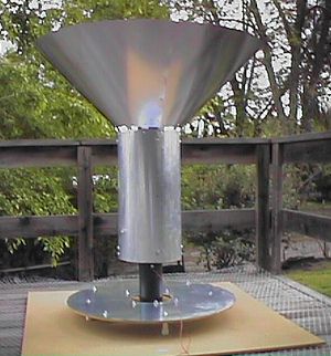
Over the past year or so since the CFA series of articles commenced, we have received numerous requests for more information about how to build a 160-meter version of the CFA. Well, here it is! The 160-meter CFA is being presented in two parts. This first part will deal with dimensions and some networks while part two will describe the details, complete with pictures of the actual construction based on one being built as this Part 1 article is written. Part 2 will appear in next month’s issue authored by Gary Nixon, WA6HZT and Jay Lemmons, N6YIP of Sacramento, California. Gary and Jay are active members of the GARDS and are doing the construction and well-qualified to do so, with amateur and broadcast experience.
The protracted period of building, testing and rebuilding, retesting of various other versions of the CFA for higher frequencies has resulted in an antenna that can be built by most who try and are diligent enough. The dimensions shown here were provided by an engineer quite familiar with the CFA and were scaled from an actual broadcast CFA. Even so, the dimensions may still be subject to some change as the optimization of the antenna is accomplished over the next few months. Not to worry as the basic configuration will be the same.
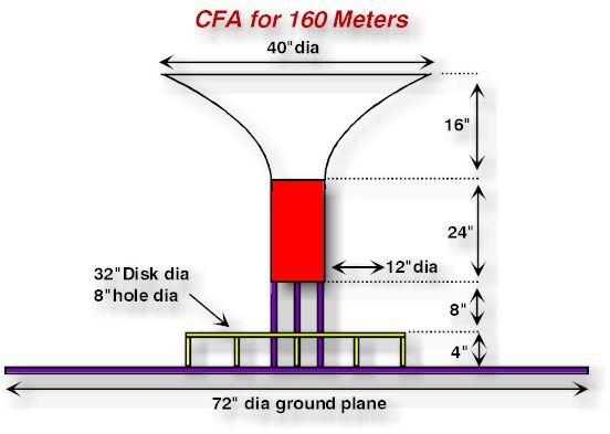
In the configuration of the antenna below showing the side view, you will notice it has the top funnel configuration that was ultimately used on the latest installations of broadcast antennas. This will be the first-known CFA amateur version to include this “hat”. One purpose of the hat is to lower the angle of radiation which is ideal for DX on 160. I do not know what the angle is with the top funnel configuration, but the absence of this gives the vertical radiation of 30-38 degrees according to some measurements made by independent groups. So you can either build your CFA with or without the hat, depending on what you want to do. Either way, you will have a much smaller antenna than a 1/4-wave vertical.
Construction of the Ground Plane and D Plate
A sheet of plywood at least 1/2-inch (1.24cm) thick should be used for the ground plane, which should have a minimum diameter of 72 inches (182.88cm). The GP could be larger, but this is considered a minimum diameter. The thickness is also a minimum. You will need at least two sheets of 4’x6’ plywood (1.22×1.82m) and will need to fasten them together in order to get the correct ground plane size. Small pieces of plywood can be used to fasten the two sections together. Then cut the GP out with a saber saw or similar cutting tool. Be sure to sand the edges of the GP smooth to prevent splinters from sticking you while working with the wood.
The D-plate is 32 inches (81.28 cm) in diameter with an 8-inch (20.32cm) hole in the center. It can be made of the same plywood thickness as the GP.
After you have cut the two elements, then decide what to put on them for a conducting surface. If you can find copper flashing and it is not too expensive, strips can be glued in place and soldered together for a solid copper surface. This may be an expensive way to go, so the use of thin aluminum sheet may be your cheaper alternative. Clean copper window screen may be used as long as it is nice and shiny. Some have used aluminum foil and as long as you are able to secure it to the plywood and make good connections between sheets, it will be okay.
Weatherproofing
Next you must weatherproof the wood and conducting surfaces. How you do this will be determined by what is available to you. Epoxy paint could be used, as could polyurethane varnish or spar varnish. Just remember you will need two contact points for connection to the D-plate across the hole and also a connection for the ground plane to a ground rod and the network ground. You also may want to add tie-down points on the ground plane to keep it from blowing over and to provide for connections to several ground rods.
Construction of the Cylinder
The cylinder may be made of sheet aluminum cut to the correct length and rolled in a cylinder of the correct diameter. Or the use of a galvanized length of outer chamber of chimney flue cut to the correct length will work. Another source of cylindrical forms is Sonotube. This is a wax impregnated cardboard tube used as a form for concrete pillars and can be found in many sizes. Check your local construction material suppliers for these forms. These can be covered with flashing and will also need some type of weatherproofing. Again, spar varnish, or polyurethane finish will do the job. In hot climates several coats will be needed to help prevent ultraviolet radiation from damaging the protective coating. Painting will not hurt any part of this antenna, as long as you do not short the antenna insulators.
Constructing the Funnel
How you build the funnel will depend on your level of construction skills. It may be made with straight sides by rolling a sheet of aluminum or alternate material used into a cone. Trim to fit into the cylinder and pop rivet in place. Then trim the top to the correct dimension. Another method is to bend either large diameter wire, such as #4 ground wire or small diameter copper pipe to the proper shape and fasten them to the cylinder. Clean copper screen may be used to cover the resulting framework. Solder the screen in place. Cover it with either paint or whatever used to coat the other elements. This will prevent corrosion. If you can come up with another way to build this section of the antenna, pass it on. Again, this section of the antenna is optional and may be added after you finish the basic antenna. It will lower your angle of radiation though if DXing is desired. There are now nearly 20 previous articles in antenneX to give you more ideas for how you can build a CFA easily. The 160 CFA is simply a little larger and the hat addition is an intriguing and useful feature.
Network Construction
The network described here is the same as originally published in the antenneX article Care & Feeding of a Crossed-Field Antenna from the February 1999 issue, now in Archive III (#18) and has been used with success by other experimenters. The only thing that changes is the tuning components. Figure 1 shows the diagram of the network. Our thanks to Stefano Galastri, IK5IIR of Florence, Italy as he tested this network on the air for some time and proved it worked for his CFA project.
L1, the matching coil can be either wound on a toroid or air wound. The toroid should be a T200-2 or equivalent (see note below for available source of Toroids) and the total turns on this toroid should be 21 turns of #14 AWG wire, with a ground tap at 12 turns. An air wound coil needs to have a few more turns in order to accomplish the matching—this is an area to modify as needed. A pair of 365 pf broadcast radio variables should do for the capacitors and the coils need to be wound with approximately 33 turns of #14 AWG wire. This will do for both L3 and L2. These components should be good for most rigs in the 100-150 watt range. By using your grid dip meter you can verify the tuning range of the coil and capacitor combination. If you do not have a grid dip meter, the alternate method is to connect the coil and capacitor in parallel and then in series with a fairly long wire 20-30 ft. long. Then connect the coil and capacitor to the antenna terminal of your rig.
Tuning is Tricky and Critical
Tune in a signal in the middle of 160 meters or just use noise for the input signal. Now, tune the capacitor through its range. If the values are correct the noise or signal will be attenuated as the capacitor hits that resonant frequency. This is an alternative method for determining resonance of a L/C combination. Conversely, if you use a series-tuned circuit, the signals or noise will go up when you hit resonance.
If you are unable to find identical capacitors, compensating adjustments must be made to the number of turns on the coils used with the individual capacitors. Again, resonance of the individual coil/capacitor combinations must be checked by one or more of the methods described above.
When you finish your network, connect it to the antenna and tune it up, using a field strength meter and an SWR bridge for maximum field strength and for minimum VSWR. As you do this, keep in mind that there are several places that will give minimum VSWR, but little radiation. You must have maximum field strength and minimum VSWR at the same time. There is a “sweet spot” that must be found and this is where some would-be CFAers fail. Watch the needle on the FSM and locate the spot where it rises to maximum and starts to fall off. Back up to that maximum spot. That’s the place. Then and only then will the antenna radiate correctly.
To Start or Wait?
I know many of you are anzious to get started on this long-awaited 160 CFA and there is probably enough information in this Part 1 of the 160-meter CFA series to go ahead and get started on your own project if you don’t want to wait for the Part 2, which will be published in the May 2000 issue #37 (due out May 1, 2000). However, be mindful that the above-described 160m CFA is under construction at this very moment and some new and useful information may be discovered along the way to completion that could prove to be a better way to optimize the device. The basic construction should be very close and if anything changes, it will most likely occur in the type of network utilized because this component of the CFA remains subject to much more experimenting and optimization. The antenna component configuration is not likely to change radically if at all, so it may be safe to start collecting your ideas of the type of materials and construction to use for your own project. This will make for a very nice spring/summer project for the upcoming 160 operations. Enjoy!
Gary’s Info
Jay’s Construction Guide
I have always been a bit of a McGyver; you know, the guy on TV that could take a radiator cap from a 1968 Chevy, two coat hangers and roll of duct tape and turn them into a one-man helicopter. The approach to building a CFA has been about the same. I wanted a structure that used common parts available from a hardware store, and it had to be cheap!
After going to our local Home Depot (a Mecca for us McGyver types) and grazing for a while we found everything for our “CFA Kit” and the total was just over a $100.00 USD. This is what we got:
Materials List
| In the Heating and Air Conditioning area: | ||
| 1 x | 12″ diameter heating duct 4′ long | To form the cylinder |
| In Roofing Materials: | ||
| 3 x | 3′ x 4′ galvanized sheet steel | This is the disk & the cone |
| In Plumbing: | ||
| 1 x | 8′ long 4″ id black PVC pipe | You can cut this in half to transport! |
| 1 x | Flange for the PVC pipe | This has four mounting holes |
| 1 x | 3/4″ PVC sprinkler pipe | Cut this if it won’t fit in your car |
| 8 x | 3/4″ PCV end caps | You DON’T need glue! |
| From the Hardware area: | ||
| 24 x | 1/4″ 20 x 1 1/2 inch bolts | This includes some extra |
| 6 x | 1/4″ 20 x 1 inch bolts | Extra here also |
| 100 x | 1/4″ 20 hex nuts | The 20 means twenty threads per inch |
| 24 x | 1/4″ flat washers | But metric would be just fine |
| 24 x | 1/4″ internal star washers | Split ring lock washers if stars are unavailable |
| 8 x | 1/4″ x 5″ carriage bolts | These were really used on carriages! |
| 100 x | 8-32 x 3/4″ machine screws | That 8 is the diameter and is a wire size |
| 100 x | 8-32 hex nuts | Cashews would be fine |
| 100 x | #8 internal star washers | Twinkle twinkle little star (washer) |
| In the Fence section: | ||
| 1 x | 25′ x 3′ role of 3/4″ hardware cloth | Chicken wire works too! |
| In Lumber: | ||
| 1 x | 4′ x 8′ sheet of 1/2″ particle board | Or plywood, you can cut into 4’x4′ |
| And, in Paint: | ||
| 1 x | Can of white spray paint | To apply to black 4″ PVC vertical support |
· Aviation Snips
· Fine file
· Tape Measure
· Slide Square
· Pencil
· 36″ string
· Drill
· 1/8″ bit
· 1/4″ bit
· 9/32″ bit
· 3/8″ bit
· 1/2″ bit (for de-bur)
· Jig Saw
· Aviation snips
· Gloves
· 7/16″ wrench
· 7/16″ nut driver
· 5/16″ nut driver
· Slot screwdriver
· Dikes
· Hand punch (optional)
· PVC cutter (optional)
· Micrometer (only required for mil spec)
· Grease pencil (only required for mil spec)
· Axe (only required for mil spec)
· Hammer (only required for mil spec)
· Paint (only required for mil spec)
· Binford CO2 cutting laser (optional)
Well, alright for the shopping adventure! Let’s head back home and get started. First a quick word about safety is in order. You will be working with sheet metal, cutting and drilling it. You can get cut if you are not careful! This should not be a big problem for anybody that can still count to ten using their fingers, but I suggest having a pair of gloves around, or a lot of band-aids. If you feel you need safety goggles, kevlar vest or a portable personal force field, have at it!
Sadly the next 2 paragraphs relate to a ZIP file that had drawings of the CFA construction, sadly these were not included under the same file structure. This also relates to a lot of missing images that were also not included, why they posted links instead of posting the files themselves I have no idea – MD0MDI
There are three drawings you’ll want to pay attention to: A top view, an elevation slice and a template for the conical section. In case you are interested the drawings were done in Microsoft Visio, a nifty drawing program, and saved as JPEG or converted to GIF files (for the web). If you would like the original Visio files so you can play with them later, you may download them at the following link as well as the program to run them (the files are compressed into “zip” files, so you’ll need an unzipping program like WinZip at www.winzip.com):
The critical dimensions are included in the drawing or comments, those that don’t matter are left for your own selection. On the elevation and top view drawings I have color-coded the metal components RED, BLUE for hardware, DARK GREEN indicates particleboard and PINK for PVC plastic.
So, let’s get started on this CFA!!! I have designed the structure for construction in several sections for ease of building and transporting. The base holds the ground screen down and provides mounts for the disk and cylinder/cone. The disk is removable and the cylinder/cone will come off. This will allow the structure to fit through a normal doorway (would not want to build a boat in a basement!)
We will start with the base. Take the particleboard and cut it into two 4-foot (1.22 m) square sections (unless it can be bought that way) and lay the sections on top of each other. In the exact center drill a 1/4″ (.64 cm) hole through both pieces at one time. Bolt them together temporarily with a 1/4″ bolt. Now lay out the pattern for the circle. You can use the 1/4″ bolt you put in the center and a string to draw a 32″ (81 cm) circle and an 8″ (20 cm) circle. Now lay out the four holes that the short PVC supports will bolt through. I suggest 12″ (30 cm) above and below, left and right of the center bolt for the location, but it is not critical at all. Drill the first of these holes (1/4″ of course) and place a temporary bolt through it. By following this process you can be assured the holes match. When that is done, drill the remaining three holes. Next place the PVC flange in the center and mark the four mounting holes. Drill them through both pieces of particleboard. At this point we have ten holes in the two boards and two concentric circles drawn on one. About 1 inch (2.54 cm) from the inner circle, drill one additional hole which will serve as a connection point for the disk.
Unbolt the two pieces of particleboard and set the one without the circles aside. Grab your trusty Binford jig saw (or you can use a Sawzall like I do!) and cut the 32″ circle on the particleboard. Just on one board, not both! It does not have to be perfect but neatness and accuracy are nice; it does not have to be mil spec though. (You know about MilSpec don’t you? Measure with a micrometer, mark with a grease pencil, cut with an axe, hammer to fit, paint to match!) Next cut the inside circle. Count your fingers—ten is the correct answer.
Grab those eight PVC end caps and poke a 1/4-inch hole in each of them, in the center of the round end. While we are playing with PVC, cut four pieces of the 3/4-” (1.9 cm) PVC 2-5/8″ (6.67 cm) long. A neat cutter is made for cutting PVC and can be found in the plumbing section of your hardware store for about $8.00 USD.
Time for the first sheet metal adventure. Using the particleboard “donut” you cut out previously as a template, mark the 32″ and 8″ circles along with the four mounting holes on one sheet of the sheet metal. Cutting sheet metal is best done with “aviation snips”, not the classic “tin snips”. The classic snips look sort of like big scissors but they can be dangerous on long cuts and difficult for curved cuts. With the angled handles and compound leverage, “aviation snips” produce a much better cut and are designed to handle curves. They are available in several configurations, starting with M1 and working upwards. M1, M2 and M3 are designed for making straight, right hand (curving to the right) and left hand cuts. Personally I use M6 snips which work well for almost any cut. Good tools are a good investment and I strongly suggest getting some of the right ones for this project. It will go smoother.
Cut the disk to the cut lines you marked. Be very careful and strongly consider wearing gloves. When you are done, use a fine file to take some of the sharp edges down a bit. Use a 9/32″ bit and drill the holes that you marked previously. You should lay the sheet metal on a scrap sheet of particle board then stand on it as you drill. De-bur the holes with a much larger bit, such as a 1/2″ (1.27 cm).
Now you can bolt the PVC end caps to the baseboard (48″ or 1.22 cm square) in four places. Lay the sheet metal disk on the particleboard disk and bolt four caps in place. Add another 1/4″ bolt 1 1/2″ (3.8 cm) long for the electrical connection hole you drilled near the center hole. Add a second nut to this bolt, forming an easy place to hook your feed wire later.
Mount the PVC flange to the 48″ square of particleboard using the holes you previously drilled. Cut two 72″ (1.8 cm) lengths of the hardware cloth and lay them out on the ground to form a 72″ square. Then lay the 48″ square on top of the ground screen, with the flange pointing up.
Earlier we cut four short pieces of 3/4″ PVC. Locate those and place one in each PVC end cap mounted on the 48″ square. Now you can set the disk on top of those four sections of PVC and insert all four. This should leave you with a disk mounted over a ground screen and you are now ready to build the cylinder.
For construction of the cylinder we are using a common sheet metal ventilation duct. These typically come in four-foot (1.2 m) lengths and have a seam that must be locked together. Before you lock the seam, cut the duct to a 24″ (60 cm) length using your trusty aviation snips. Remember the gloves and count you fingers when done (hint: ten is still the right answer!)
The cylinder is mounted to the PVC center tube in four places at each of two levels, both at 3″ (7.6 cm) in from the respective ends. Mark these at 90-degree points around the cylinder and drill them 1/4″. I recommend starting these holes with a small pilot hole first. On the feed (lower) end of the cylinder, drill two additional holes 180 degrees apart where you will later connect the feed wire.
Cut the center PVC tube to 40 inches (102 cm) and measure up 14 1/2″ (37 cm) from one end and drill four holes 3/8″ (1 cm) diameter at 90 degrees around the tube. Measure up another 18″ (46 cm) and drill four more holes. Keep them in the same rotation around the tube, so if you were to look down the center of the tube the holes are aligned rotationally. IMPORTANT: If black PVC is used, be sure to paint it white, using the can of spray paint on the Materials List. Do this BEFORE assembly. I’ll explain why later.
Reach for the 3/4″ tube and cut eight lengths that are 3 3/4″ (10 cm) long. After closing the seam on the cylinder you are ready to attach it to the tube. Using your hand, reach into the cylinder with a carriage bolt and start it though the hole (if it will not fit, use your drill to “angle” the hole to allow the bolt to go through). Slide one of the 3/4″ tubes over the bolt then, with the tube inside the cylinder run the bolt through one of the holes in the cylinder. Put a flat washer and star washer on before the nut and just firm it up by hand. Repeat this seven more times. Be sure you have the connection holes (those that are 180 degrees apart) at the end of the tube you measured from.
When all of the bolts are in, slide the end of the tube through the hole in the center of the disk and into the flange. Tighten up the eight bolts, but do not over-tighten, then cut off any excess bolt. Expect some of the center tube to stick out the top.
To connect to the cylinder I drilled two holes in the tube so I could run a wire straight through from one connection hole, through the holes in the tube, to the other connection hole. Just below these two new holes in the tube, at 90 degrees to the wire and about 4 inches lower, I put in a bolt as a connection stud and wired the two connection points to that stud with #12 wire.
This builds the basic CFA without a cone. Our cone was built with sheet metal but the fun was calculating the template. I have reduced that down to a MS Excel spreadsheet which is shown here.
This will allow you to quickly generate dimensions for other cones or even compound cones.
Here is a drawing of the flat sheet to show you where the dimensions apply. During design we cut this out like a paper doll and made a paper cone! Using the template diagram, you can get two petals out of each 3′ by 4′ (.9 x 1.2 m) sheet of metal. Mark up one, cut it extra carefully, then use it as a template. Pay careful attention to the holes so they match up. I suggest you drill or punch all four sheets at the same time and bolt together with the first couple of holes.
On the subject of holes, I have a great little hole punch made by the Roper Whitney company that punches up to a 9/32″ hole. It was only about $40.00 USD but that was twenty five years ago! You can find these at Heating and Air Conditioning suppliers. It’s much better than drilling!
To mount the cone to the cylinder I made a dozen tabs and used 8-32 hardware. Mark up the tabs using some of the sheet metal scrap. Cut one long piece first, then drill or punch the holes. Afterwards you can cut the tabs apart. This will avoid slicing and dicing your fingers as you drill.
Mount the tabs to the cone and bend them. To mark the cylinder, hold the cone in place (get some help) and mark the top of the cylinder. Punch or drill those holes then set the cone back in place and bolt it up.
If you are going to leave the antenna in an area where you think the wind will severely distort the cylinder, you can tie it to the extended center post with plastic clothesline. Now you know why the center post was left long.
If you wish to protect the structure, a cold galvanize compound, available in a spray can will help. Afterwards normal painting finishes the job. Another thing we noticed afterwards is that with the Sun shining into the cone will tend to heat up and MELT the black 4″ ID PVC vertical support! The solution is simple: from the list of materials, we added a can of white spray paint to apply to the black PVC support section that will prevent the reflected sunlight from melting the PVC. Be sure to do this before assembly.
So, are you totally confused? Check the drawings and it should make sense. If you really get stuck, shoot me an email (jay@lemmons.com) and I will try to help out. Overall this should be a one day project for even a beginning McGyver. The final check, can you still count to ten? Congratulations!
Gary’s Back Now
How well does it work? It’s too early to tell for sure, but we’ve had some very encouraging early results. We spent most of the available time this month constructing the CFA, with very little time left over to try networks (more on that in a moment). One short distance QSO on 1997 kHz the evening of April 22 was made using approximately 25 Watts on SSB with a station about 100 miles away. The network for that contact was NOT optimized, but I can tell you this:
With those 25 Watts and an unoptimized network, my CFA signal was S9 100 miles away! Now, thanks to this new Internet media, hear what we first heard on the CFA recorded in streaming audio! Below are three separate audio files. First, listen to the audio of the QSO made right after hookup of the CFA. Then, secondly, listen to an audio of the follow-up report on the QSO I filed exclusively for antenneX after talking to the other operator by landline two days later. I think you will agree, as he and I did once all the operating parameters were known, that the performance of the little CFA was pretty amazing, all things considered. Thanks to Wes, W6YWH, for being the other half of the first-known 160-meter CFA QSO! As you can hear from the third audio file below, I also did a bandscan highlighting a few other 160 signals on the evening of April 23, so you could get a feel for how the antenna “listens”, and it’s included it here.
Jay and I intend to test several more networks over the next few weeks and report back on our findings. We also intend to publish calibrated field strength data from this antenna and the various networks we will construct. The one glaring item lacking from all the CFA material available today is hard performance data. Realistically, we do not expect to crack the deepest secrets of the CFA or it’s matching network in the next month (although it would be nice surprise!). After all, Dr. Kabbary has spent 10 years on just that! What we do hope to achieve is a network and antenna configuration that will allow acceptable 160-meter operation from places where it would otherwise be impossible. That, and the first set of hard data, taken at several monitor points, with a commercial grade, calibrated field strength meter.
One thing that will help speed things along is an invention Jay (McGyver) brainstormed: A network “breadboard”. All the network components are placed on a common work area with short interconnection wires, allowing for partial or complete network reconfigurations in a matter of minutes, and all without heating up a soldering iron! It’s a real dream for those of us who perpetually ask, “What if I did this…???”; the time and effort saved is substantial. We’ll detail the construction of the network breadboard, as well as report our field strength measurements, in Part III of this CFA series. Until then, 73!…Gary and Jay
Gary’s Introduction
Our hope in building and experimenting with the small, conical section CFA was to find a set of conditions where 160-meter amateur radio operation could be reasonably accomplished in a four-foot tall package. “Reasonable” being a subjective word, we considered an efficiency on the order of 25% or greater to be an acceptable level of performance, given that we are still learning how the CFA works, and it would afford those that may not otherwise have an opportunity to operate on 160 meters a chance to do so, albeit at somewhat of a deficiency.
In preparing for what we anticipated to be a long series of trial and error network configurations (we weren’t disappointed), Jay designed a network “breadboard”, so we could easily build networks up from schematics and try new ideas without a lot of down time. It works great! If you are looking for an advantage in your network building adventures, this approach is worthy of consideration. Here’s Jay with the construction details on the one we used:
The Network Breadboard
Many years ago radios were built on breadboards; literally, boards with components screwed in place with wires running between them. Many of these were true works of art and are cherished collectors items today. The term “breadboard” has been part of the electronics industry ever since.
Having tried many of the networks proposed for the CFA, Gary and I grew tired of the hot glue gun, winding coil after coil, and tedious network construction. So, the Network Breadboard was born!
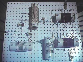
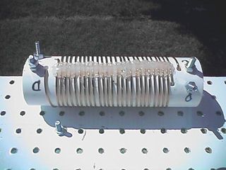
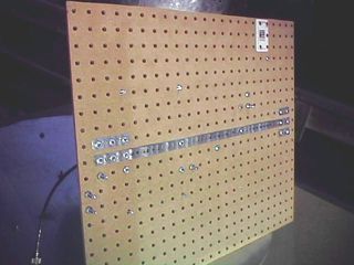
Using components from our local hardware store, we constructed a group of generalized components that could be moved around to different configurations and rewired as needed, all without the “fun” of hot glue guns and solder. The unit is based upon a heavy pegboard. This masonite board is larger than the one you may be familiar with, and has 1/4″ holes spaced on a 1″ grid. It is usually available with one white-sided surface. We bought a 2′ by 4′ piece and cut it down to two square pieces of 2 feet x 2 feet. You can make them any size you wish, perhaps one larger then the other. If you don’t have a saw that works well for this, most hardware stores will gladly cut the board for you.
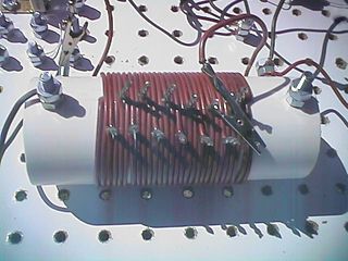
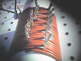
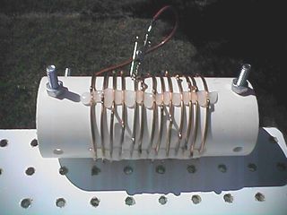
Now we needed components; coils and capacitors. For coils a section of 2″ PVC plastic pipe was cut into 9″ lengths. Using a 1/4″ drill bit, four holes were made 1/2″ in from the edge of each end or 8″ apart. Using 1/4″ hardware, bolts were put in place as mounting holes and terminations for coil windings and taps. As a picture is worth a thousand words, below are four of the variants we have constructed:
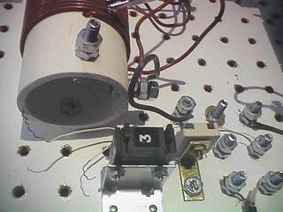
- Capacitors were mounted on brackets found at the hardware store and mounted on the breadboard. One version used a digit switch and 100 pF capacitors to form a binary stepper capacitor that ranged from 0 pF to 1500 pF in steps. We also used small compression trimmers ranging from a few hundred to well over one thousand pF. Above is a picture of the capacitor.
- Inputs and outputs were done via more 1/4″ hardware, and the intercomponent wiring was simply 14-gauge electrical wire, the same as we used to wind the coils.
Experiment with your own designs for the breadboard components, the goal is to be able to change designs at will with minimal fuss. Now, back to Gary…
How We Doin’?
The larger part of this story is our degree of success in getting the CFA to perform decently. We discovered some interesting phenomena over the past few weeks, and will share them with you now.
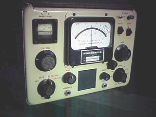
For the record, we used an MFJ-259B Antenna Analyzer as the signal source. It delivers 7.8 milliWatts (mW) into 50 Ohms, as read on an IFR-120B service monitor. Field strength readings were taken using a Potomac Instruments FIM-41 Field Intensity Meter at .36 Kilometers from my home. I will refer to this location as the “reference point”.
It should be noted that a standard reference antenna must be used in evaluating the performance of any other antenna system. Such a reference “antenna” is available from the Federal Communications Commission, the regulatory agency in the USA responsible for radio communications. They offer an on-line utility (http://www.fcc.gov/mmb/asd/figure8.html) where you input the parameters of an antenna system and it will calculate the expected field strength.
It was this utility that was used in assessing the performance of our CFA. We configured the reference antenna as being one of 44.1 meters of height at 1700 KHz (as high in frequency as the utility will calculate, and certainly close enough to 160 meters for our purposes), with 120 44.1-meter-long radials. This is the equivalent of a quarter wavelength radiator over 120 quarter wavelength ground radials, theoretically a fully efficient antenna system. Using this configuration, we should realize a field strength of 865 microvolts (uV) at 1 Km., or 2400 uV (2.4 millivolts) at the .36 Km reference point, with 7.8 mW of power.
With those preliminaries out of the way, here are some of the discoveries. I found that moving the CFA off the ground (soil conductivity in this area is approximately 15 ms/m) up to my wooden deck (36” above ground) almost doubled the field strength! This may account for all those roof-mounted CFA’s!
Another thing I “discovered” in trying various network configurations is that they all behaved differently, efficiency-wise. Now, this may seem obvious, but I wasn’t taking anything for granted. In essence, I simply confirmed what we all expected: There are radical performance differences between network designs.
For instance, the “classic” antenneX network, the one as used by Stefano in his article of last year, produced just 14 uV of signal at the reference point with the CFA sitting on the ground. Moving the antenna up to the deck gave me 25 uV, or almost double the field intensity, but still a very poor performer. Of note is that the deck, being 36” above ground, is exactly one half the size of the ground plane dimension (72”) above ground. There may be a correlation between those figures.
The next significant results were achieved using network #7 of Heikii Antman’s, from his article in last month’s issue of antenneX (now in Archive IV). With no other changes besides reconfiguring the components, the signal doubled to 48 uV at the reference point. This still isn’t good performance, but at least we were going in the right direction!
The last published network that gave us a significant increase was one described by Maurice Hately in an obscure article he wrote on the CFA and its Implications for Military Radio. It was written for the Journal of the Royal Signals Institution and appeared in their Summer 1991 issue (ISSN ![]() 0374-3519, Vol. XX). I figured, if it was good enough for submission to such a prestigious publication as that, it was well worth the effort to try it on our little 160-meter antenna. I was not disappointed!
0374-3519, Vol. XX). I figured, if it was good enough for submission to such a prestigious publication as that, it was well worth the effort to try it on our little 160-meter antenna. I was not disappointed!
That configuration TRIPLED the field strength to 150 uV! Still not great, but better than some mobile installations, and over ten times better than where we started.
What makes this particular network unique and intriguing is that it uses a step-up transformer between the D plate and ground plane. In the schematic of the network in the article, it shows a step-up ratio of 1:3 (2 Primary windings, 6 Secondary windings).
If you are a serious student of the CFA, you might consider acquiring a copy of the article. Beyond including the only network design I have seen to use a step-up transformer, there are also qualified field strength measurements of the CFA’s versus dipoles that indicate comparable high efficiencies.
I first became aware of the Hatley article in “The Roar of Controversy” by Richard Morrow, K5CNF, published in the September 1999 issue of antenneX. You may view Richard’s article at http://antennex.com/library/shack/Sep99/roar.htm . Jay and I tried several different step-up ratios and combinations, including transformers wound on toroids and open air (PVC) forms, and didn’t get much beyond that original 150 uV figure. We had to face the facts: Our CFA was not “CFA-ing”. It became obvious something else was required.
That “something else” was a trip back to the basics. From what we have been told over the years, the E and H fields must meet within the CFA’s IZ (interaction zone) at approximately equal levels and in quadrature phase. We measured the phase of the “Hately network” and found that it was not producing the proper phase shift. This is not necessarily the fault of the design! The component values are the key to accomplishing quadrature phase, and those component values are frequency dependent. In our case, our interests are in 160-meter operation, so Jay went back to the drawing board to determine network components that would deliver quadrature phase on 160 meters. Here’s Jay again…
Introducing the T-Network
Assumptions can be dangerous. Certainly assumptions are an important part of the scientific process, known there as theory. But the trick is, assumptions or theories ultimately must be tested and mercilessly discarded if proven false. There have been many assumptions with CFAs, some of which are false. I will disprove at least one of these assumptions here.
Most phasing systems I have seen proposed for the CFA have made certain assumptions. That is fine if the assumptions are correct, a waste of time if they are not proven wrong quickly.
One of the agreed upon parameters required for CFA operation is quadrature, where the two driving signals are ninety degrees out of phase. This has been a difficult measurement for most experimenters, but a key one for alignment of a phasing system, for if the load impedance is incorrect, a network will never produce the desired signal parameters at the antenna elements. Let me explain a bit.
I use a digital oscilloscope to check the drive to the CFA elements for signal level and phase when tuning a CFA, with the MFJ bridge as the signal source (about 8mw). A 90-degree phase relationship has been the tough parameter to achieve and using the scope quickly validates any design or tuning.
One of my past activities included building dozens of antenna phasing systems for all power levels, tower counts, patterns and such. In doing this I had the pleasure of learning from one of the best minds in AM broadcast antenna systems. This learned fellow truly made it look simple, as only a real professional can do. I was recalling the lessons I had learned from those days when it suddenly became obvious that a phasing system for a CFA could be treated just like any other two-tower array! We have two driven elements, a set of desired drive parameters, element “base” impedances, mutual coupling between elements and all the other particulars of a traditional broadcast array. Now we are talking about something I can design! Or, anyone can design!
Dusting off the broadcast engineering brain cells that have laid dormant for over a decade, I dug up the formula for a “T network”. The name comes from the appearance of the schematic (as you’ll see below), where there are three elements, each reactance being either a coil or capacitor (or in some cases both). The input component (the left part of the horizontal top of the “T”) predominantly changes the input impedance. The output component (the right part of the top) predominantly changes the output impedance. And the shunt component predominantly changes the phase lead/lag of the network. I say predominantly as there is a degree of interaction which varies depending on the individual network’s parameters, but it does serve as a guideline for which knob to turn.
Here is the formulae:
R1 Input resistance
R2 Output resistance
X1 Input component reactance
X2 Output component reactance
X3 Shunt component reactance
B Phase lag (-) or lead (+)
X3 = square root ( R1 x R2 ) / sin (B)
X2 = ( R2 / tan (B) ) – X3
X 1 = ( R1 / tan (B) ) – X3
Really fairly simple, and even better when placed in an MS Excel spreadsheet (click for spreadsheet calculator). Based upon these formulas, this sheet calculates a two-element phasing system that allows you to adjust the power ratio between elements as well as the phase. Simply enter your desired values in the yellow areas and instantly you will get a phasing system design! Note: If you don’t have a copy of MS Excel on your computer, download a free MS Excel Viewer from this URL in order to see the calculator.
One advanced trick is to try different phase values ranging between plus and minus ninety degrees. As you move this value for one of the networks, the other will change automatically to maintain the 90 degree, or quadrature, difference in the output. The benefit of trying these different phase shifts is simply component selection. You are able to change the size of the coils and capacitors; in particular, reducing coil values to a lower, more manageable value. To aid in that, a section of the spreadsheet details the smallest and largest component values.
So, we merrily built a test T network based upon these formulas and hooked it up to a handy 375 Ohm resistor (actually four 1500 Ohm resistors in parallel, if you want to be picky). Using a capacitance meter and the MFJ bridge we dry-tuned (adjusted to the design value) each component. Hey, it worked! The adjustments did what they should, the phase shift was adjustable, and the scope showed it all, plain as day!
Now we connected it to the CFA structure and tuned it up. Well not up; there was no quadrature! Ouch! It was there a moment ago when the resistors were our load…??? And they were correct, within a fraction of a percent of free space impedance, 377 Ohms. What was going on?
Then reality slapped me in the head! The element impedance was certainly NOT 377 Ohms, not by a long shot. I had assumed (there is that dangerous word!), as had many others (trying to make myself feel better!) the element impedance was 377 Ohms. Wrong!
As the network we had built was expecting a load of 377 Ohms, and was driving one that was much higher, it would never produce the phase shift! To prove that theory (now another assumption) we quickly measured the impedance with the MFJ bridge and used a rough number of 750 Ohms as a starting point. If the results of the dry tune were much closer to theoretical, then we would know the theory was correct.
It was! Now the networks tuned like they were meant to, and we had quadrature clearly displayed on the scope! The VSWR was low where it should be and the input was 50 Ohms.
One of the significant points here is the removal of the network design from the CFA experiments. If we are able to truly measure phase and voltage at the drive point of the disk and cylinder, it will not matter how that drive was created. It will reduce the number of variables in the experiment and allow concentration on the CFA side of the antenna.
Further, if we have accurate element impedance values, the drive power can be calculated through Ohms law. This may not sound like a big deal, but it is. By knowing the input power to the elements, rather than simply using the transmitter output power (network input power), calculations of the CFA effectiveness can be made based solely on the CFA, totally ignoring the network losses. Once the CFA performance is maximized and the phase and voltage measured, network designs can be optimized.
One of the design difficulties encountered is the high ratio of impedance between input and output. To reduce that task I added a tank network for insertion between the T network and the elements.
These are simple to construct, composed of a coil and capacitor at resonance and two taps, one near the ground end for the input and one near or at the high end for the output. At resonance the phase shift from input to output is zero. The impedance translation can be calculated as the ratio of the squares of the “turns ratio”, with our 28-turn coils and a 4-turn input the ratio is 50 to 1.
Further work needs to be done on accurately measuring the element impedance. I have a bridge enroute that will allow such measurements and I will forward the information via antenneX when done. However, modeling with 2500 Ohms as the impedance is certainly closer to reality.
T-Network Performance
In satisfying all published criteria for proper CFA operation, we must establish benchmarks and eliminate further assumptions. If the CFA works when quadrature phase and matched levels are achieved, we now have an antenna whose performance we can control. If not, we have learned that factors other than phase and level are required to successfully operate a CFA.
And, the latter is decidedly the case. With the T Network we were able to achieve quadrature phase and vary drive levels and impedances, but did not achieve a field strength greater than that of the Hately network. We approached it, maybe even equaled it, but never significantly surpassed it. It should be noted that we tried varying height and grounding configurations, as well as countless network component variations, in our experiments.
While we may have missed the mark in achieving a “reasonably” efficient CFA, I believe we have learned much in documenting what does not work. Also, know that we were testing network configurations up to the last possible second before press time (which probably didn’t do anything good for Jack Stone’s stress level)! In other words, we readily offer that much more experimentation is called for. We tried as many things as we could before we had to stop. We simply ran out of time in order to meet press deadline. As is the case with all experimentation, this article should be considered a snapshot of a work in progress.
You might be interested to know that during the course of testing all these networks, I had the privilege of swapping a couple of emails with Dr. Brian Stewart, one of the three men most closely associated with the CFA. I asked Brian if he would be interested in settling the CFA controversy once and for all by helping us achieve a high level of efficiency with this antenna. We would then be able to document those findings conclusively, and deliver them to the world via antenneX.
While Brian and I were busy dodging the effects of the “Love Bug” virus, Brian wrote back that, after consulting with the other members of the CFA team, they felt it was in the best commercial interest of the CFA to not release proprietary technical information; hence, he was sorry, but could not help. We were disappointed, of course, but understand their position. Dr. Stewart was most gracious in his communications, and, as he did with our CFA endeavors, we wish him and the other team members well with theirs.
There are several points of discovery we have made in this month’s adventure:““““
· CFA element impedance is in the neighborhood of 2500 ohms
· A tank (resonated) transformer can bring that impedance into a reasonable value
· T networks can predictably generate the needed phased feeds
· Measurement via an oscilloscope quickly validates the element feeds
It’s been quite a month since publishing our last construction article in Part II of this series. We sincerely hope we have helped open the doors to further, successful experimentations with the CFA. We’d like to know of your adventures with this latest CFA tool, the T Network calculator, and the 160-meter CFA.
Originally posted on the AntennaX Online Magazine by Richard Morrow, K5CNF
Last Updated : 28th May 2024