4-30 MHz LPDA Design Concepts
Government, military, and some commercial enterprises have employed wide-range LPDAs for coverage of the HF region from about 4 to 30 MHz. The appeal of using a single antenna for the entire frequency range is multi-faceted. A single antenna permits frequency scanning and rapid changes of frequency without the need for antenna retuning or switching. The directional pattern of the LPDA offers gain in the desired direction at all frequencies, as well as QRM and QRN reduction from other directions.
A Review of single LPDA Design Potential
However, the single LPDA designed to cover the entire HF spectrum from about 4 to 30 MHz suffers some serious limitations. In a pair of articles in QEX (“Notes on Standard Design HF LPDAs,” May-August, 2000), I explored some of the problems and pitfalls of designing LPDAs with a wide passband–something of the order of a 10:1 frequency range. It may be useful to review some of the outcomes of the study.
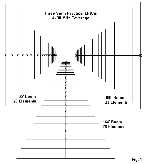
Figure 1 provides outlines of three different LPDAs, each the best of its boom length used in the earlier study. The following table provides some of the basic data about each antenna model.
| Boom Length (feet) | Number of Elements | Phase Impedance | Stub Element | Treatment | |
|---|---|---|---|---|---|
| 1. | 65′ | 20 | 200 | No | Tau-tapered diameter |
| 2. | 100′ | 23 | 200 | Yes | Tau-tapered diameter |
| 3. | 164′ | 26 | 100 | Yes | Tau-tapered diameter |
The reference to Tau-tapering of the element diameter refers to increasing the diameter of each element–referenced to the most forward elements–by the inverse of the value of Tau used to establish the basic design. In general, element diameters ranged from 0.5″ for the forward element to about 6.5″ for the rear-most element. This practice maintains a relatively constant length-to-diameter ratio for the design.
The shortest LPDA in the lot was specifically designed for 4-30 MHz and has a 132.1′ rear element. The longer boom designs set the low frequency cut-off at 3 MHz and have a 167.3′ rear element.
The following graphs explore the performance potential of the resulting LPDAs in 0.25 MHz increments. To make the graphs readable, I have divided each parameter into 2 charts, one covering 3.5-17 MHz, the other covering 17.25-30 MHz. Vertical axis scales have been matched so that the two graphs for each parameter will join seamlessly.
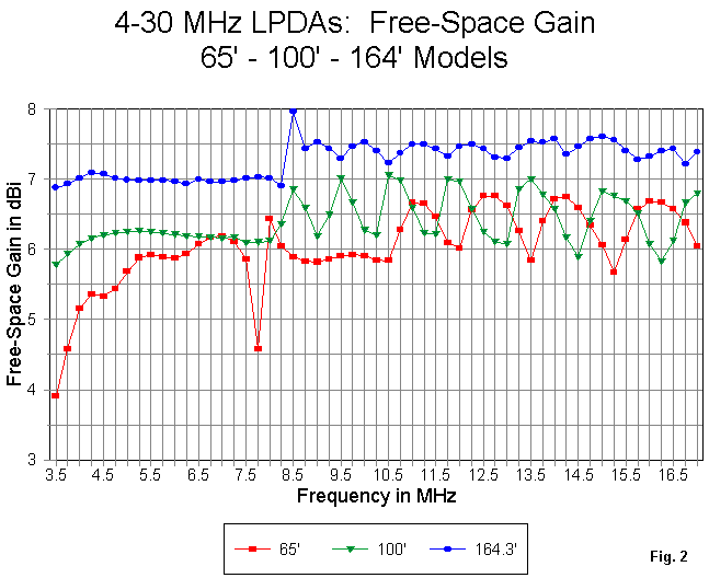
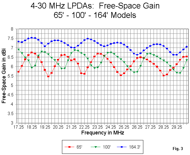
Figure 2 and Figure 3 provide the gain potential of the LPDA designs. The shortest- boom model is obviously gain deficient until it reaches 5 MHz or higher. As well, it exhibits an obvious weakness at about 7.75 MHz. Above 10 MHz, the average free-space gain fluctuates around the 6 dBi mark.
The 100′ boom model has no obvious weaknesses in gain across the spectrum, but the added 35′ of boom and 3 additional elements only raises the average gain to about 6.3 dBi (free-space). However, the 100′ boom length is already a major mechanical challenge for support and rotation.
The longest model averages just above 7 dBi free-space gain, with one odd peak at 8.5 MHz. To achieve this gain, we need at least 26 elements and a boom of nearly 165′.
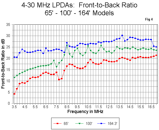

Figure 4 and Figure 5 present the potential 180-degree front-to-back ratio performance potential of the big LPDAs. Only the longest LPDA model sustains a front-to-back ratio of better than 20 dB. The mid-size model achieves that level of performance above about 8 MHz, while the shortest model slowly approaches the 20 dB level in the 12-14 MHz range. Below 5 MHz, the front-to-back ratio of the 65′ model drops below 10 dB.


The VSWR curves of Figure 6 and Figure 7 use different reference impedances. Each reference value was chosen to provide the flattest possible SWR curve. Of the three wide-range LPDA models, only the longest maintains an SWR of less than 2:1 across the design range (with a 75-Ohm reference). The mid-size model, using a 95-Ohm reference, shows significant peaks above 2:1 in the upper frequency region–where SWR in the HF region becomes a more important factor in terms of line losses. The shortest model, using an 85-Ohm reference, shows similar upper HF peaks as well as some narrow peaks at the low end of the spectrum.
Not evident in these graphs is the very high variability in the behavior of the antenna patterns. The shorter the boom length, the wider the frequency range over which we encounter pattern distortion. The forward lobe may be shaped like a garden spade or even develop a minor double lobe. Rear patterns tend to broaden so that the 180-degree front-to-back ratio is no longer a reasonable guide to rear lobe behavior. Rear side lobes down by only 15 dB are common. These expanded rear lobes are marks of incipient harmonic activity in lobes to the rear of those most active at a given frequency. Hence, the problems increase with frequency.
If we take these models as typical of LPDA performance for the boom lengths indicated–and well-engineered exceptions certainly are possible–we are faced with a dilemma. The shortest boom is most easily maintained at operating height but has marginal performance at best. However, to attain performance roughly on a par with a 2-element quad–but across the wide passband–we need boom lengths that present very major mechanical challenges. The challenges do not merely include erecting the array, but also involve wind, snow, and ice load factors.
The single LPDA for the entire HF range concept arose over 20 years ago. At that time, the basic idea was a single antenna for a single receiver or transceiver, with a single feedline coming to the equipment’s single antenna connection. In the intervening years, a number of technical advances have appeared that seem not yet to have affect HF LPDA use for complete spectrum coverage. Perhaps it is time to rethink the LPDA for 4-30 MHz.
Not 1, But 3
In the intervening years, a number of techniques for antenna selection or “polling” have appeared, and the technology is widely applied to cell and related services wherever higher gain and narrower beamwidth antennas are required. Such techniques might easily be applied to wide-range HF service as well.
In addition, for most applications requiring the coverage or scanning of the entire HF range, neither resources nor real estate are a major problem. Hence, one might well erect multiple towers, each one holding an LPDA optimized to the degree possible for a portion of the total frequency range. The feedlines can be brought to a central location for polling and then routed to the equipment.
The entire 4-30 MHz range is nearly 3 octaves in bandwidth. We may easily subdivide the design problem into 3 roughly 2:1 frequency-range models. 2:1 bandwidth LPDAs are significantly easier to design than a single antenna with nearly a 10:1 frequency range. To make the design challenge more difficult but the mechanical and maintenance problem less daunting, let’s set a 50-56 foot limit to the boom in each case.
It might be tempting to suggest placing all three antennas on a single rotating tower. Such a system might well be made to work in some cases. However, it presents another dilemma. Mechanically, the antenna for the lowest portion of the range wants to rest at the lowest of the 3 levels, where mechanical support is greatest. However, electronically, it needs to be at the highest level for transmitting and receiving effectiveness in terms of lower elevation angles of radiation.
For the moment, we can set aside the problem of support systems and look in a more focused way at the electrical design of the individual LPDAs. For convenience, we shall divide the spectrum into 3 sections. The Low Range will run from 4 to 7 MHz. The Middle Range will cover 7 to 14 MHz. The High Range will complete the picture with 14 to 30 MHz coverage. The ratio of highest to lowest frequencies for each antenna increase with frequency, since we have limited the boom length. It is easier to reach beyond the 2:1 target ratio at the upper HF region than it is even to reach that ratio at the low end of the spectrum.
As well, the system of LPDAs in this design exercise has considerable overlap, as shown in the following table:
| Range | Boundary Frequency | Low Frequency Limit for <2:1 vswr | High Frequency Limit for <2:1 vswr | Overlap as a Percentage of Boundary Frequency |
|---|---|---|---|---|
| Low | 7 | 3.75 MHz | 7.70 MHz | 12% |
| Middle | 14 | 6.85 | 15.4 | 16% |
| High | — | 13.1 | 30+ |
The overlapping coverage of the arrays points to a further advantage of a triple LPDA antenna farm for covering the HF spectrum: if one antenna suffers damage, the other two remain in operation. As well, some of the gap in coverage is filled by the remaining antennas.
The three antennas forming the array for this exercise have the following basic properties.
| Range | Number of Elements | Boom Length (feet) | Element Size (inches) | Element Type | Tau | Sigma | Phase Line Zo (Ohms) | Stub |
|---|---|---|---|---|---|---|---|---|
| Low | 13 | 53.0′ | 2.5-6.4″ | Tau-taper | 0.9245 | 0.0250 | 200 | Yes |
| Middle | 16 | 56.17′ | 1.0″ | Aluminium | 0.9300 | 0.0400 | 150 | Yes |
| High | 22 | 55.83′ | 0.5″ | Aluminium | 0.9500 | 0.056 | 100 | No |
In all three designs, the value of Tau was kept high to maintain a relatively high element density for better low-end performance. As well, the highest frequency of use was set well above the highest frequency to be used to sustain gain at the upper spectrum end. However, each antenna in the set presented unique design challenges, so each deserves an individual examination.
The Low-Range LPDA

Figure 8 provides an outline of the low-range antenna designed to cover 4 to 7 MHz. Clearly apparent is the relatively close spacing of the elements that results from the selection of a low Sigma value. Indeed, the value of Sigma is below that recommended in design calculations. Hence, the design was developed by a good bit of trial-and-error modeling. The values of Tau and Sigma, suited to the design length of the boom, also dictated the narrower frequency coverage for this array (1.75:1).
The low-range model has some interesting features. First, it is the only model of the set to require Tau-tapered elements to achieve the design goals. The elements range from 2.5 to 6.4 inches in diameter, as shown in the following partial model table.
13 el 53′ 3.8-7.5 MHz Frequency = 4.35 MHz.
Wire Loss: Aluminum — Resistivity = 4E-08 ohm-m, Rel. Perm. = 1
Wires
| Wire | End 1 X (feet) | End 1 Y (feet) | End 1 Z (feet) | End 2 X (feet) | End 2 Y (feet) | End 2 Z (feet) | Diameter (inches) | Segments |
|---|---|---|---|---|---|---|---|---|
| 1 | 0.000 | -64.729 | 0.000 | 0.000 | 64.729 | 0.000 | 6.41E+00 | 29 |
| 2 | 6.559 | -60.750 | 0.000 | 6.559 | 60.750 | 0.000 | 5.93E+00 | 27 |
| 3 | 12.622 | -56.435 | 0.000 | 12.622 | 56.435 | 0.000 | 5.48E+00 | 25 |
| 4 | 18.228 | -52.173 | 0.000 | 18.228 | 52.173 | 0.000 | 5.07E+00 | 23 |
| 5 | 23.410 | -48.233 | 0.000 | 23.410 | 48.233 | 0.000 | 4.69E+00 | 21 |
| 6 | 28.201 | -44.591 | 0.000 | 28.201 | 44.591 | 0.000 | 4.33E+00 | 19 |
| 7 | 32.630 | -41.223 | 0.000 | 32.630 | 41.223 | 0.000 | 4.00E+00 | 17 |
| 8 | 36.724 | -38.110 | 0.000 | 36.724 | 38.110 | 0.000 | 3.70E+00 | 17 |
| 9 | 40.509 | -35.417 | 0.000 | 40.509 | 35.417, | 0.000 | 3.42E+00 | 15 |
| 10 | 44.009 | -32.667 | 0.000 | 44.009 | 32.667 | 0.000 | 3.16E+00 | 13 |
| 11 | 47.244 | -30.167 | 0.000 | 47.244 | 30.167 | 0.000 | 2.93E+00 | 13 |
| 12 | 50.235 | -28.750 | 0.000 | 50.235 | 28.750 | 0.000 | 2.70E+00 | 11 |
| 13 | 53.000 | -26.583 | 0.000 | 53.000 | 26.583 | 0.000 | 2.50E+00 | 11 |
The stub used in the model is 1.5′ of 600-Ohm shorted line.

The free-space gain of the array from 4 to 7.5 MHz appears in Figure 9. Only above 7 MHz does the gain drop below 6 dBi. (Do not let the steep curve mislead you into thinking that gain varies by a wide margin. The Y-axis spreads a relatively small range–0.5 dB–over a large linear distance.) The gain in this frequency region is similar to that of the 100′ wide-range model, but with half the boom length. For the remainder of the frequency span, gain will be higher. Indeed, part of the design conception was to limit lower gain performance to the smallest possible portion of the entire passband. No other combination of Tau and Sigma within the general limit of the boom length approached these gain figures for the entire 4-7 MHz range.

The 180-degree front-to-back ratio shows, in Figure 10, generally increasing values as the frequency increases. Although low by upper HF standards, the values are in keeping with the general gain levels shown in Figure 9.

Figure 11 provides a 60-Ohm referenced VSWR curve for the array. It surpasses 2:1 at two points: at 6.5 and 7.25 MHz. In general, VSWR values above 2:1 but below 2.5:1 may be considered acceptable in the lowest portion of the spectrum where even coaxial cable losses are close to negligible at these levels. If equipment is sensitive to the reflected voltage taken from a line sample, one might well add one of the newer automatic antenna tuners to the line to ensure full power output.
Short-boom LPDAs for the lower HF range press LPDA design not only up to its limits, but beyond. However, by judicious experimental modeling, it is possible to design an acceptable LPDA for the lowest frequency range without limiting the remainder of the HF spectrum to the same level of performance. Even a 53′ boom length will present mechanical challenges, since the elements will be very long. The longest element is nearly 130′. The design element diameter can be approximated either through the use of open-frame triangular structures or by multiple strands of widely spaced wire.
The Mid-Range LPDA
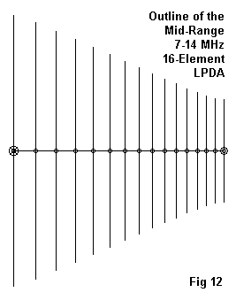
As shown in Figure 12, the mid-range LPDA in the set is quite standard in appearance. The 16-element design using 1.0″ diameter aluminum elements requires a 56.17′ boom and a 150-Ohm phase-line. The following wire table provides element details.
.93/.04 6.88-15 MHz Frequency = 13 MHz.
Wire Loss: Aluminum — Resistivity = 4E-08 ohm-m, Rel. Perm. = 1
Wires
| Wire | End 1 X (feet) | End 1 Y (feet) | End 1 Z (feet) | End 2 X (feet) | End 2 Y (feet) | End 2 Z (feet) | Diameter (inches) | Segments |
|---|---|---|---|---|---|---|---|---|
| 1 | 0.000 | -36.200 | 0.000 | 0.000 | 36.200 | 0.000 | 1.00E+00 | 27 |
| 2 | 5.904 | -34.150 | 0.000 | 5.904 | 34.150 | 0.000 | 1.00E+00 | 27 |
| 3 | 11.395 | -31.915 | 0.000 | 11.395 | 31.915 | 0.000 | 1.00E+00 | 25 |
| 4 | 16.501 | -29.681 | 0.000 | 16.501 | 29.681 | 0.000 | 1.00E+00 | 23 |
| 5 | 21.250 | -27.603 | 0.000 | 21.250 | 27.603 | 0.000 | 1.00E+00 | 21 |
| 6 | 25.667 | -25.671 | 0.000 | 25.667 | 25.671 | 0.000 | 1.00E+00 | 21 |
| 7 | 29.774 | -23.874 | 0.000 | 29.774 | 23.874 | 0.000 | 1.00E+00 | 19 |
| 8 | 33.594 | -22.203 | 0.000 | 33.594 | 22.203 | 0.000 | 1.00E+00 | 19 |
| 9 | 37.146 | -20.649 | 0.000 | 37.146 | 20.649 | 0.000 | 1.00E+00 | 17 |
| 10 | 40.450 | -19.203 | 0.000 | 40.450 | 19.203 | 0.000 | 1.00E+00 | 15 |
| 11 | 43.522 | -17.859 | 0.000 | 43.522 | 17.859 | 0.000 | 1.00E+00 | 15 |
| 12 | 46.380 | -16.609 | 0.000 | 46.380 | 16.609 | 0.000 | 1.00E+00 | 15 |
| 13 | 49.037 | -15.525 | 0.000 | 49.037 | 15.525 | 0.000 | 1.00E+00 | 13 |
| 14 | 51.520 | -14.654 | 0.000 | 51.520 | 14.654 | 0.000 | 1.00E+00 | 13 |
| 15 | 53.892 | -14.042 | 0.000 | 53.892 | 14.042 | 0.000 | 1.00E+00 | 11 |
| 16 | 56.167 | -13.692 | 0.000 | 56.167 | 13.692 | 0.000 | 1.00E+00 | 11 |
The 72.4′ longest element will likely require an equivalent diameter considerably in excess of 1 inch, while the 27′ shortest element might well have an equivalent uniform diameter closer to a half inch. Tau-tapering the elements in this array had no significant effect upon the performance. However, a shorted stub consisting of 2′ of 600-Ohm line proved useful.
Although the bulk of the elements adhere to the 0.93 Tau and 0.04 Sigma values, the rear-most and forward-most elements were subjected to Tau-circularization to optimize performance. A close look at Figure 12 will reveal that the element tips do not form a straight line, but a small ogee curve.

As shown in Figure 13, the average free-space gain of the array is between 7.1 and 7.15 dB, about the same as the gain of a 2-element quad. Note that this performance was achieved only by the 164′ full-spectrum LPDA model–about 3 times longer than our mid-range LPDA. Because the boom length has been limited, resulting in a fairly low value of Sigma, the upper end of the spectrum shows increasing fluctuations, for a total gain variance of about 0.35 dB from 7 to 14 MHz. The gain drops below 6.9 dBi only within the overlap region with the high- range LPDA.

Figure 14 shows the 180-degree front-to-back ratio across the passband. The ratio remains above 20 dB, with well-control rear lobes, up to 14 MHz.

The 50-Ohm SWR curve in Figure 15 shows the mid-range LPDA to maintain under 2:1 across the pass band. The curve would be slightly better using a reference impedance of 55 Ohms.
The mid-range LPDA is in every way conventional, including the circularized Tau factor used to modify the original design that emerged from initial calculations. It provides good performance for the boom length and number of elements.
The High-Range LPDA
The high-range LPDA requires only scant comment, since it has appeared before in these pages.

As the outline in Figure 16 reveals, the design is the same 14-30 MHz design on a 55.83′ boom developed in detail in the past few months. The design uses a parasitic director to enhance upper range performance more than circularizing Tau alone can do. The following wire table will review the dimensions.
14-30 MHz .95/.056 21+dir 55.8 Frequency = 28 MHz.
Wire Loss: Aluminum — Resistivity = 4E-08 ohm-m, Rel. Perm. = 1
Wires
| Wire | End 1 X (feet) | End 1 Y (feet) | End 1 Z (feet) | End 2 X (feet) | End 2 Y (feet) | End 2 Z (feet) | Diameter (inches) | Segments |
|---|---|---|---|---|---|---|---|---|
| 1 | 0.000 | -18.025 | 0.000 | 0.000 | 18.025 | 0.000 | 5.00E-01 | 25 |
| 2 | 4.015 | -17.083 | 0.000 | 4.015 | 17.083 | 0.000 | 5.00E-01 | 23 |
| 3 | 7.829 | -16.167 | 0.000 | 7.829 | 16.167 | 0.000 | 5.00E-01 | 23 |
| 4 | 11.452 | -15.367 | 0.000 | 11.452 | 15.367 | 0.000 | 5.00E-01 | 21 |
| 5 | 14.894 | -14.598 | 0.000 | 14.894 | 14.598 | 0.000 | 5.00E-01 | 21 |
| 6 | 18.164 | -13.868 | 0.000 | 18.164 | 13.868 | 0.000 | 5.00E-01 | 19 |
| 7 | 21.271 | -13.175 | 0.000 | 21.271 | 13.175 | 0.000 | 5.00E-01 | 19 |
| 8 | 24.222 | -12.516 | 0.000 | 24.222 | 12.516 | 0.000 | 5.00E-01 | 17 |
| 9 | 27.025 | -11.890 | 0.000 | 27.025 | 11.890 | 0.000 | 5.00E-01 | 17 |
| 10 | 29.689 | -11.296 | 0.000 | 29.689 | 11.296 | 0.000 | 5.00E-01 | 15 |
| 11 | 32.219 | -10.731 | 0.000 | 32.219 | 10.731 | 0.000 | 5.00E-01 | 15 |
| 12 | 34.623 | -10.195 | 0.000 | 34.623 | 10.195 | 0.000 | 5.00E-01 | 15 |
| 13 | 36.907 | -9.685 | 0.000 | 36.907 | 9.685 | 0.000 | 5.00E-01 | 13 |
| 14 | 39.076 | -9.201 | 0.000 | 39.076 | 9.201 | 0.000 | 5.00E-01 | 13 |
| 15 | 41.137 | -8.741 | 0.000 | 41.137 | 8.741 | 0.000 | 5.00E-01 | 13 |
| 16 | 43.095 | -8.304 | 0.000 | 43.095 | 8.304 | 0.000 | 5.00E-01 | 11 |
| 17 | 44.955 | -7.888 | 0.000 | 44.955 | 7.888 | 0.000 | 5.00E-01 | 11 |
| 18 | 46.722 | -7.494 | 0.000 | 46.722 | 7.494 | 0.000 | 5.00E-01 | 11 |
| 19 | 48.400 | -7.119 | 0.000 | 48.400 | 7.119 | 0.000 | 5.00E-01 | 9 |
| 20 | 49.995 | -6.763 | 0.000 | 49.995 | 6.763 | 0.000 | 5.00E-01 | 9 |
| 21 | 51.510 | -6.425 | 0.000 | 51.510 | 6.425 | 0.000 | 5.00E-01 | 9 |
| 22 | 55.833 | -7.392 | 0.000 | 55.833 | 7.392 | 0.000 | 5.00E-01 | 11 |
The feedpoint is on wire 21, and the phase line for this model is 100 Ohms. (The 250-Ohm phase line model uses a 14.2′ element for wire 22.) The following graphs are presented to show performance below 14 MHz as well as within the design passband.

Figure 17 shows the gain curve at 0.25 MHz intervals. Note that this close spacing of check point reveals two relatively weak region: at 19.75 and 26.5 MHz. One or both of these regions can be virtually eliminated by adding a shorted stub to the rear of the assembly. Neither is so serious as to reverse the antenna pattern, but both show that even with relatively high values of Tau and Sigma, harmonic operation of elements to the rear of the most active element may still occur.
The free-space gain drops off rapidly below 14 MHz, but remains above 8.2 dBi at 13.25 MHz. The parasitic director permits a free-space gain above 9.0 dBi at 28.25 MHz and higher.

The 180-degree front-to-back ratio, shown in Figure 18, reaches 20 dB by 13.75 MHz and remains above that value until 29.5 MHz. The exceptions are the two weak regions previously noted. The weaknesses can be removed by using a 250-Ohm phase line. Using this line will lower the gain slightly across the passband and result in a feedpoint impedance best referenced to about 110 Ohms. A 2:1 wide-band transmission-line transformer balun would provide a satisfactory match to a 50-Ohm cable.

Figure 19 provides the VSWR curve relative to a directly fed 50-Ohm feedline. The SWR drops to under 2:1 by 13.1 MHz. Only in the upper region of the passband–largely as a result of adding the parasitic director–does the SWR approach 2:1.
With high-range LPDA performance that is superior to the mid-range LPDA down to 13.1 MHz, the crossover point between the mid-range and the high-range LPDAs is a matter of choice at installation. The overall free-space gain of the high-range array averages about 8.8 dBi, with a superior front-to-back ratio.
Conclusion
Three 55′ booms just about equal the total boom length of the 164′ wide-range LPDA. However, each of the individual LPDAs with an approximate 2:1 frequency span manages patterns that are better behaved. The use of three separate arrays confines lesser performance to the frequency region where it may be necessary, with increasingly better performance as we move up in the frequency regions. As well, the use of separate arrays and electronic selection and/or polling offers at least partial system operation should one antenna be down for maintenance.
The triple LPDA array is an expensive proposition, best fit for military, governmental, or commercial applications calling for relatively complete coverage of the HF spectrum. The present design exercise has attempted to see if there might be an alternative to the use of single arrays with somewhat marginal performance in such applications. Using 3 LPDAs, each optimized to a portion of the spectrum, provides increasingly better performance within the 55′ boom limitation.
It is possible, in principle, to build an unconditionally stable LPDA to cover the range from 3 to 30 MHz. The free-space gain will range from a low of 10.25 dBi to a high of about 11.35 dBi, using a Tau of 0.955 and a Sigma of 0.18. Unfortunately, this 60-element antenna will be just short of 1250′ long.
Perhaps three relatively short LPDAs are not so bad after all as a substitute.
References


Originally posted on the AntennaX Online Magazine by L. B. Cebik, W4RNL
Last Updated : 5th June 2024

