
Starting Your First VHF Station
An Introduction
Of some interest to me was the lack of interest in the 222 to 225 MHz area. As many know who have experienced operation on the “220 Band” (most still refer to it as such), this is a great piece of spectrum for repeater as well as simplex operation. It is a near perfect region sporting a low-level noise floor with reasonable path loss. I am sure the attraction on 2 meters as well as .75 meters is the abundance of repeaters in operation as well as available equipment both new as well as “Already Burned In” equipment. (Auto dealers would call these Previously Driven Rigs!)
In response to these requests, I will cover the areas of major importance for the new buyer to think about when getting ready to lay down hard-earned cash that will allow getting the most equipment for the lowest cost and still obtain the features required. I will base my discussion on 2-meter equipment due to its popularity. Please understand however that the basic guidelines and buying tips presented will apply to any of the “VHF-UHF” frequency bands of operation. The areas selected to be discussed are the transceiver and its power supply, along with a suitable antenna and cable system to meet the needs of intended operation, as well as the restraints of your bankroll! I will assemble a 2-meter station as an example and discuss emergency backup power for a new system. There will be a detailed article titled “Emergency Backup Power” on this subject coming soon in antenneX!
For the Necomer to VHF Radio
Prior to laying your money down at the radio shop counter, or ordering through a mail order sales supplier, or a purchase through a personal transaction, there are several things you should give just consideration to prior to spending that first dime! As an example, what band or bands of operation do you want to work? Six meters? There are some great band openings on six FM as well as SSB. The sun spot cycle now upon us is making this a hotter band for both long as well as short range “Skip” operation at this time. In the larger cities of the USA there are frequently a good number of FM repeaters in operation on the six-meter band.
Two meters is the most popular of the VHF bands by far. This may provide a good opportunity for a new operator to contact many stations in the area of operation (usually within a 50 to 100 mile radius of the repeater site), make new friends and learn more about your hobby through practice. Sometimes however, often within the larger city areas, LA, NY, Chicago, Boston and so forth, things can get a bit too busy. If you are thinking about 222 MHz operation, be certain to check with other local area hams to see how much activity there is on the 222 to 225 MHz band in your area. 220 MHz is perhaps the least popular band for repeater operation. This is sad because it has so much going for it as mentioned in my introduction.
The 430 to 450 MHz (75cm band) is the next most popular band for FM repeater operation. This area of operation has several major advantages not found on two meters. Although the frequencies between 144 to 148 MHz (2 meters) are very quiet in comparison to Six meter or Ten meter operation, for those that have privileges there, 440 MHz is a very quiet place to operate from. The antennas are much smaller for the same gain, but point to point simplex operation takes a bit more effort than it would on 2-meters to cover the same distance. This can be compensated for by using higher gain antennas, higher power from your transmitter and getting an increase in your receiver sensitivity using a pre-amp or through a good alignment. The antennas on 440 portables are generally shorter than those on two meters (6-inch 1/4-wave length compared to a 19-inch 1/4-wave length for 2-meters). They tend to be more efficient and the portables are easier to handle. (More detail on portables in Part-2 of this article.)
So, item number one is the selection of the band or bands you wish to operate on and which modes of operation. AM is rarely used in the VHF frequency range with a few exceptions, such as “50.4” MHz on 6 meters. SSB is quite popular on the low end of Six meters and to a lesser degree on 146 and 430 MHz. There is a good deal of SSB activity to be had in most areas of the USA. However, FM and to a lesser degree, Packet, are the major modulation sources on the Two-meter band. CW is rarely heard except for the ID’er at your repeater.
Listening In
I often suggest to new users of the VHF-UHF spectrum to invest in a scanning receiver to monitor the frequencies in the area you wish to operate. Even the least expensive scanning receivers will provide FM coverage from 29 to 512 MHz. Also be sure they will provide 222 to 225 MHz coverage if you have any interest in this area of operation. There are a great many used scanners available at very reasonable prices (frequently check the classified ads in the NEW antenneX Classified Clearing House). Take a bit of time to listen to the difference between the different bands. How the operators on each band conduct themselves and the range obtained by different repeater systems. This is also a good time to select an antenna for general purpose monitoring, or one designed specifically for a band or bands of interest that may later be used for operation on that band when you are ready to “Start Talking.” A very inexpensive general coverage ground plane antenna for your scanner receiver is sold by Radio Shack for $35 (USA$) RS-# 20-014. This antenna will cover 30 through 512 MHz with unity gain. With antennas in mind, let’s begin there and work ourselves down to the power plug or battery power supply for your transceiver.
Selecting an Antenna
We will make the assumption, at this point, that your band of choice will be 2-meters (operation on other bands will logically follow the same concepts). Your mode of operation will be FM voice communication with the thought you may wish to add Packet operation at a later date. Let’s also assume your average elevation is approximately +100 feet (30.5 m) and the repeater of primary interest to you is on a mountain top at an average elevation of 1,000 feet (305 m). Further you have a line of site, unobstructed view, of the repeater site from your antenna at a distance of approximately 25 miles (40 km). Although this description is a bit ideal it’s a place to begin. Under these conditions, it should be no problem placing a very solid signal into the repeater from your location using a unity gain, omni-directional antenna with 10 watts or less transmit power. This would indicate that you could buy or build a simple 2-meter, Unity Gain, Ground Plane antenna and have good results. This is always a good way to start and will keep your antenna cost in the $10 range (USA$). (See the November Issue of antenneX, Ham WorkShop for details).
It is prudent to consider purchasing or building your own omni-directional (transmits & receives in all directions equally) antenna for your initial installation. One other source is to look for a used, but in good condition, 2-meter antenna from another Ham that has moved up to the “Gold Plated, Super Signal, Electron Accelerator” antenna (Hi-Hi) and may no longer have use for his “Ringo Ranger” or ??? When selecting an antenna, there are several important items to consider. If you do not give these points due consideration you may become very unhappy with 2-meter operation quickly. Antenna effectiveness is much more pronounced as you move up in frequency to 220, 440, 900 MHz or 1.2 GHz operation. Selecting the wrong VHF-UHF antenna for your situation is very similar to the gentleman who purchased a beautiful, full-featured stereo system with all of the bells and whistles at a cost of $2,000 (USA$) and then connected this stereo masterpiece to a pair of cheap $15 (USA$) speakers and cannot understand why the sound is so poor!!
An old rule of thumb: “Under most circumstances, if you have a choice between adding $100 (USA$) to your antenna system or that same $100 for additional ‘Bells & Whistles,’ go for the improvement to your antenna system”! This will include the antenna, mounting mast or tower and a very important item, often overlooked—the quality of your feedline cable. As an example, by moving to a 5/8-wavelength ground plane, or a J-Pole antenna (which will add about 3 to 3.4 dB gain to your radio system in comparison to a simple ground plane antenna) will double your output power, as stated before, and increase your receiver sensitivity by a like amount. You may also take the option of spending less for a lower transmit power transceiver, smaller power supply to operate it also, and allow the few additional dollars spent on your antenna to compensate for the lower power, less costly, transceiver. Again, 25 watts at your 3 dB gain antenna will provide an Effective Radiated Power (ERP) of 50 watts!
At VHF-UHF frequencies, feedline losses (expressed in dBs per length of cable) increase rapidly with increasing frequency. As one quick example, a 3-dB signal loss in your feedline cable will cut your power at the base of the antenna to one half! That’s a 50% loss just in the coax cable between the antenna and your transceiver. Your new 45 watt 2-meter “Blitz Bolt” transmitter will be delivering only 22.5 watts to the antenna! You will also incur this same 3-dB signal loss to your receiver. The coaxial cable you select to feed your antenna system is very important!
Antenna Types & Polarization
Perhaps the most talked about subject between Ham Radio operators is that of antennas. Pick any frequency, or frequency band and there will be fifty different antennas to discuss and about 100 opinions as to “which one tops which one!” This is nothing new to our hobby. VHF-UHF frequencies just add several more “Antenna Flavors” for us to chew on. As a positive note, there are antennas that can be constructed in the VHF-UHF frequency range that are impractical to build at HF due to their large physical size alone. This is one advantage of operating on these 50 MHz plus frequencies!
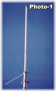
Virtually all FM and Packet activity on 2-meters is vertically polarized (see Photo-1).
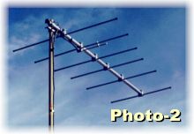
Most all Single Side Band (SSB) activity is conducted in the horizontal mode (see Photo-2). For our work throughout this article we will be referring to Vertical Polarization. Vertical polarization was chosen in the early days of 2-meter FM repeater activity, some 35 years ago, because it is easy to provide an omni-directional signal from a mountaintop if you use the vertical mode. Horizontal mode antennas for mobile units are cumbersome. The commercial communications industry was also firmly fixed on a vertical format as well. In that era, some 35 years ago, almost all FM transceivers were converted single or dual channel Motorola, GE or RCA outdated commercial “Two-Way” radios from the fire or police department. If you found a four-channel rig, you then had some “Bragging Rights”! Oh, they were loaded with little glass bottles inside that glowed in the dark called “Tubes”?? Technology has sure changed!
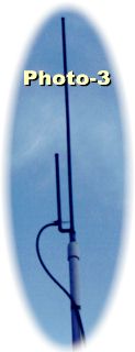
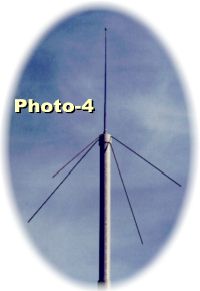
There are two major categories of vertical antennas we will discuss at this juncture. First on our list (and the type most frequently used) are omni-directional antennas. Antennas of this type come in many shapes and forms. (See Photos-1, 3 & 4) Their designs provide ranges of gain from 0 dB (unity gain) to over 9 dB. This would provide your 2-meter transceiver with a gain of over eight in comparison to a basic ground plane shown in Photo-4. Gain antennas are more costly and are in general much taller as the gain increases.
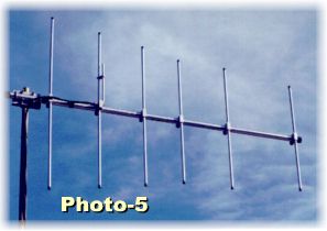
The second antenna type is a directional antenna (see Photos-2 and 5). As shown, this Yagi, or Beam antenna, may be mounted in the horizontal or vertical position as desired for your use. The antenna shown has a forward gain (gain in one direction only) of about 9 dB. It also has a “Negative” gain or “Null” to the rear. This is a desired feature if you are bothered by other signals on your frequency coming from the rear of your antenna. With the addition of an antenna rotator you will be able to “Point” your beam in any direction desired. This can become very useful when you are some distance from one or more repeaters you wish to work through that are in different directions from your location. It is also very useful for working mobile or fixed stations on a simplex frequency.
To this point I have provided the basic information you may need to select the best antenna for a new station setup. In review, your first choice is polarization and we have a given situation that it will be “Vertical” unless your interest is in SSB.
Next on our checklist is a directional or omni-directional antenna. I usually advise to most “new to the band” that they select a 3+ dB gain antenna for starters. This antenna type will provide useful gain in all directions at a reasonable cost of $30 to $50 (USA$). It will also provide a basis to judge the performance of any later upgraded antenna you select. If you do desire to improve your antenna system at a later date (we all plan on that!) it is very useful to have a second antenna for test or a monitor receiver as an example. I monitor 146.52 MHz, the National Simplex Frequency for 2-meters, 24/7 at my QTH.
If you are located some distance from the repeater or packet site you wish to reach, then a fixed or rotated beam with a minimum gain of 6 dB might be the best choice. If you live in an urban area and are surrounded by repeaters, you may desire to use a unity gain ground plane or vertical dipole. Here again, unless you are restricted by available space or housing area covenants, you may be much happier using the suggested 3-dB antenna such as a gain ground plane or a J-Pole design. You can never go too far wrong using this type of basic gain vertical antenna to get your station on the air.
Selecting the Feedline
As mentioned earlier in this article, the selection of coaxial cable “feedline” for your 2-meter radio system is very important to your station’s overall operation. The “loss” comparison between RG-58 and RG-8 @ 150 MHz is rather large. A 100-foot (30.5 m) length of RG-8/U coax will show a loss of 3.2 dB at 150 MHz in comparison to RG-58/U that will increase your signal loss to 6 dB. A 6-dB loss in your transmission line is equal to reducing the output of your 40 watt 2-meter transmitter to only 10 watts at the antenna! Transmitter power is an expensive part of the cost of a new transceiver. There will always be some amount of line loss to be dealt with and the object is to keep it to a minimum.
Please refer to Table-1 as a reference guide to determine the cable type you have or want to select for use with your station. The standard measurement frequency of 150 MHz was used at a length of 100 feet (30.5 m). The loss expressed in dB is directly proportional to cable length. If, for example, RG-8/U is selected, its loss is shown as 3.2 dB per 100 feet. A fifty-foot length of this same cable would only insert a line loss of approximately 1.6 dB. It is important to keep your cable length to a practical minimum.
Cable Insertion Loss at 150 MHz, 100-Foot (30.5 m) Length
| Cable Type | Cable Loss Comments |
|---|---|
| RG-58C/U | 6.6 dB Very short cable runs, Test Cables |
| RG-58U | 6.0 dB Very short cable runs, Test Cables |
| RG-8U | 3.2 dB OK up to 30 feet (9.15 m) |
| RG-8U FOAM | 2.2 dB OK up to 45 feet (13.7 m) |
| 9913 (Belden) | 1.7 dB Recommended for all installations |
| .5 Inch “Hard Line” | 1.0 dB Excellent but may be cost prohibitive |
I would suggest, for any cable length up to 30 feet (9.15 m), the use of RG-8U. Or better yet, use RG-8 Foam that will not introduce excessive loss. For lengths exceeding this I would strongly suggest moving up to the Belden 9913 coaxial cable. It can be used with standard “N” or “UHF” connectors and will cut your line losses almost in half! It is a more costly product, but it is a “One Time” purchase that will continue to provide a low loss path to your antenna for many years to come! Also referenced in Table-1 is .5 inch (1.27 cm) “Hardline.” Hardline is an expensive, low-loss cable that received its name due to the solid aluminum or copper outer shield instead of the standard braided shield. It is available in sizes from .5 inch (1.27 cm) to over 2 inches (5.08 cm) in diameter! The connectors for hardline are also very costly.
So Watch Those Losses!
To this point we have started with your proposed antenna, (where else would an antenneX article start?) and worked ourselves down to the connector of your 2-meter transceiver. I hope I have clearly conveyed the understanding that at frequencies from 2-meters up your signal losses mount up quickly. Coaxial cable inherent losses top the list. Please remember, poor solder joints, improperly terminated cable-connector junctions, dirty or corroded connectors or connectors that are not weather tight will also contribute to your losses. Once again, keep in mind, all loss between your antenna and transceiver will affect both the transmit power and the receive signal strength equally. If you improve one you get the other as a bonus.
I am also developing a “Frequently Asked Question” Guide to aid new operators in this neat world above 50 MHz! Your input, with questions, in reference to this article or any other related question you may have or feel appropriate for the new operator will be greatly appreciated. The one question you ask may be of value to hundreds of other Ham Radio Operators in more than 170 countries!
Originally posted on the AntennaX Online Magazine by August Hoecker, W8MIA
Last Updated : 26th April 2024