Self-Contained Vertically Polarized Wire Antennas
Notes on the family of self-contained wire verticals (SCVs) and some quantification from models.
Proponents of deltas, half-squares, and DMS (double magenetic slot) antennas for 160-40 meters find them both simple and useful for DX. All exhibit low angles of radiation without higher angle lobes. Hence, while gain cannot compete with some other antennas, the signal-to-noise ratio for DX is superior. The antennas act like a natural filter against higher angle QRM and QRN.
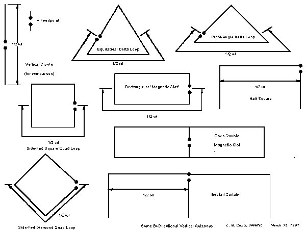
Some folks do not realize that all of these antennas share properties that make them members of the same family. Besides the elevation pattern shown below (which is broadside to any of the antenna structures), they share these properties:

- All use about 1 wavelength of wire (except for the “doubles”). As with all 1 wl systems, properties can be altered by selecting the feedpoint on the system.
- All are closed systems, independent of the ground as the completion of the antenna. Like all antennas, they depend on ground quality in the long measure for effective reflection. However, unlike vertical monopoles, the local ground beneath the antenna does not figure into their basic efficiency or operation to any significant degree. In other words, they model correctly in free space and work very well at VHF many wavelengths above the ground.
- For vertically-polarized operation, all are fed 1/4 wl from a high- voltage node. For delta loops, this is 1/4 wl down the sloping side of the antenna from the top apex. For rectangles, diamonds, and squares, the feedpoint is mid-side, which places it 1/4 wl from the high voltage point at the antenna mid-top. For the half square, which is usually operated pointing down at lower HF, the feedpoint is at the corner junction of the vertical and horizontal elements.
- Low horizontal members act largely as phasing lines rather than as radiators. The high voltage junctions effect a phase reversal so that anywhere along the line relative to center, the currents are of equal magnitude but opposite phase. This has the effect of largely, but not perfectly, canceling horizontally polarized radiation. (For the half square, operated pointing down, the horizontal line is at the top.)
Notice that understanding the operation of these antennas does not require resort or appeal to concepts like ground planes, slots, or other terms some invoke to make their antennas special. A DMS is nothing more than a vertically polarized rectangle, similar in principle to a side-fed square.

Here are the basic configurations of the self-contained wire verticals:
As a check on these antennas, I modeled each in free space at 7.15 MHz. Here are the dimensions (rounded) of the antennas modeled.
| Antenna Name | Abbreviation | Dimensions |
|---|---|---|
| Equilateral Delta | Eq Dlt | 48.8’/side, base down, apex up |
| Right-Angle Delta | RA Dlt | 60.8′ base, 43′ sides, base down apex up |
| Square Quad | Square | 36.3′ per side |
| Diamond Quad | Diamond | 36.3′ per side |
| Rectangle (DMS) | Rect | 58′ horizontal, 12.8′ vertical |
| Double DMS (K5RP)* | DMS2 | 56′ horizontal, 16.5′ vertical; far end crossed |
| Open Double DMS (K4VX)* | Open DMS | 110.8′ horizontal, 11.1′ vertical; center vertical wire; fed on end wire |
| Half Square | HS | 62.4′ horizontal; 39′ verticals |
| Bobtail Curtain* | Bobtail | 125′ horizontal; 38′ verticals; fed on center wire |
* Indicates a double (2 wl) version of the basic 1 wl antenna. Some antennas use a common center vertical wire, which can be treated as two wires in parallel and carries twice the current of the end vertical wires.
Here are free space performance figures, that is, azimuth gain figures and feedpoint impedances:
| Antenna | Gain (dBi) | Feedpoint Impedance (ohms) |
|---|---|---|
| Eq Dlt | 2.9 | 120 |
| RA Dlt | 3.3 | 51 |
| Square | 3.2 | 130 |
| Diamond | 3.1 | 130 |
| Rect | 4.4 | 15 |
| DMS2 | 4.7 | 80 (2wl systems) |
| Open DMS | 5.7 | 30 (2wl systems) |
| HS | 4.6 | 65 |
| Bobtail | 6.3 | 40-70 * (2wl systems) |
*The Bobtail can be fed almost anywhere along the center vertical. At the junction with the horizontal wire, the feedpoint impedance is near 40 ohms; at the midpoint, the impedance is closer to 70 ohms; about 60% up the vertical, the feedpoint impedance is about 55 ohms.
In practical terms, the Open DMS or the Rectangle may be much preferable for 80 meters; while the half square and bobtail come into their own at 40 meters. See especially ON4UN’s Low Band DXing for further variations on these antennas, although he does not recognize them as a single group and has not sorted out ground condition from monopole completion factors in the matter of ground radials. Other antenna books and manuals seem to treat each of these antennas as a singular type.
Since we do not get to place our 40-meter wires in free space, some sense of real-world performance seems necessary to get a feel for these antennas. In the real world, there are too many possibilities to catalog, but perhaps a single example may be helpful in getting started. Thus, I created a 40-meter antenna builder’s comparison, setting certain common limits to antenna height and taking into consideration minimum heights above ground. In general, for this exercise, 50′ was the maximum height arbitrarily selected. Closed antennas had a minimum height requirement of 20′ for safety from a low horizontal wire. Some antennas had to violate these limits or be omitted. The Half Square and Bobtail verticals had a minimum heigfht of 10′, since there was no horzontal wire at this level to create hazards to humans. Within these limits, here are the performance results.
| Antenna | Height Range | Gain (dBi) / To Angle (degrees) | Feedpoint Impedance (ohms) |
|---|---|---|---|
| Eq Dlt | 10 – 52.3 | 1.1 / 21 | 160 |
| RA Dlt | 20 – 50.4 | 1.9 / 19 | 60 |
| Square | 20 – 56.3 | 1.6 / 18 | 145 |
| Diamond | 20 – 71.4 | 1.5 / 16 | 135 |
| Rect | 37.2 – 50 | 3.0 / 17 | 15 |
| DMS2 | 34.5 – 50 | 3.3 / 17 | 80 |
| Open DMS | 38.9 – 50 | 4.5 / 16 | 30 |
| HS | 11 – 50 | 3.4 / 19 | 45 |
| Bobtail | 11 – 50 | 5.0 / 18 | 40 ** |
** 40Ω for Corner-fed, 56Ω for 60° up, 70Ω for Center-fed
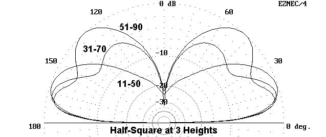
To meet the ad hoc building constraints, the Equilateral Delta and the Diamond must be eliminated, and the Square is close to elimination. The Equilateral and Right-Angle Deltas can be operated with the horizontal wire at the top for some improvement in performance. Likewise, one can operate the Half-Square and the Bobtail with the horizontal wire at the bottom, although this places the high current nodes close to ground and presents additional mechanical problems to the builder. From the perspective of performance, the Half-Square and the single-loop DMS Rectangle are the best low angle antennas, while their double-size counterparts improve performance further. One constrant on the Half-Square and Bobtail is that one cannot raise their height too far (higher than about 30′ at the bottom on 40 meters) without the appearance of a secondary lobe at a higher angle. The rectangular and other closed loop antennas can be raised much higher without the formation of the secondary lobe.
In the end, each builder must create his own comparison chart to account for local restrictions and opportunities. However, these numbers might be useful as a start in better understanding the members of this interesting family of antennas–the SCVs (self-contained verticals).
How High Should I Place an SCV?
This question is reasonable, because the behavior of the elevation pattern of SCVs is far less familiar than patterns for dipoles and Yagis. In fact, it may come as a surprise.
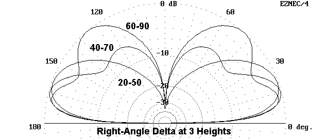
The elevation angle of an SCV is largely controlled by the peak height of the antenna. For the lowest lobe, this ranges from about 20 degrees for a maximum height of 50′ down to about 13 degrees for a maximum height of 90′ up. Of course, there is serious energy below the elevation angle of maximum radiation.
However, some folks are surprised to learn that as they elevate one of the SCVs, a second lobe appears and comes to dominate the pattern. In the figure is the same 40-meter right-angle delta with vertical dimensions of 20 to 50′, 40 to 70′, and 60 to 80′ upward. 50′ is under 1/2 wl (closer to 3/8 wl). Its pattern is the purest, with only a single lobe and a field maximum at 20°. The model with a maximum height of 70′ (just over 1/2 wl) shows the appearance of a secondary lobe at a much higher elevation angle. The lower lobe, although at 15 degrees, is not stronger than that of the model 20′ lower, and radiation at 10° and below is insignificantly different. The model at the highest level (90′ or about 5/8 wl) has a lower lobe at about 13°, but it is now lesser in strength than the main lobes of the lower models. The maximum radiation appears at nearly 50°, and the two lobes blend together for single wide elevation pattern between about 10° and about 60°.

This same pattern development is inherent to all versions of the SCV antenna family–a genetic trait. As the figure shows, one can see this in a half-square modeled at vertical dimensions of 11 to 50′, 31 to 70′, and 41 to 90′ up. A secondary lobe at a high angle appears at the middle height, while that secondary lobe becomes the primary lobe at the upper height.

What does all this mean? The answer depends on two key factors. First, as the upper-angle lobe grows, so too does higher angle QRM/QRN to reduce the signal-to-noise ratio of low-angle signals. since gain at the lowest levels does not change significantly, the added noise will make DX harder to hear.
Second is the type of operating an individual wishes to do. For DXers, the heights above the lowest level may do more harm than good. However, for general operation in both domestic and international competition, the highest model may provide the broadest signal coverage, although the middle-level models may equalize the stronger closer signals with the more distant weaker signals. Remember that these patterns affect the strength of both transmitted and received signals, and both should enter into one’s deliberations.
These patterns hold good for the lower HF bands when model heights are scaled for the frequency of operation.
Originally posted on the AntennaX Online Magazine by L. B. Cebik, W4RNL
Last Updated : 13th March 2024
