17 Meter Simple Beam
Since the opening of the WARC bands for amateur use there has been very few beams for either of the two located at 18 MHz and at 24 MHz.
This will describe a simple beam that has been around for many years in one form or another. This particular version is a wide spaced version of the ZL Special.
Most of the other versions were close spaced, usually under .25 wavelength, with .125 wavelength being the most common. In my own experience, using a close spaced 10-meter version several years back, when ten was heading for the bottom of the cycle, I worked an average of 5 new countries per week. The rig was a Radio Shack ten-meter rig, with 25 watts out. So, I can safely say that the antenna works well.
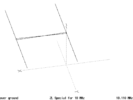
In Figure 1, you can see the basic configuration of the beam. It is a phased array type of antenna, with the two elements out of phase 180 degrees. This is accomplished by feeding the rear element after hooking up the coax to the front elements. Connect the centre conductor of the coax to the Right Front Element and the shield to the Left Front Element, viewing the antenna from the front. Then the interconnecting coax is hooked up with the centre conductor being connected to the Left Rear Element. The shield is connected to the Right Rear Element. You do not have to use coax, but can use bare wires, suitably spaced, and insulated from each other or use twin lead. Just remember the phasing. Twist the two wires 180 degrees from front to rear. Of course, you must waterproof all connections.
CONSTRUCTION METHODS
Since this is a very simple beam, how you build it is up to you. What I did for my 10-meter version was to use the stressed beam method by which I constructed the frame out of PVC and then pulled the elements, which in this case were made from twin DC lead, tight by pulling the PVC into a bow for both elements. So, my antenna looked like two bows separated by the boom which was a 2×2 that had been waterproofed and was clamped to the mast by a muffler clamp.
This is one way to build the antenna, but I would recommend the use of aluminium or cheap copper tubing. Aluminium is getting rather costly and 15mm copper tubing which is used in plumbing is a little cheaper depending on where you live. The copper can also be soldered to and should be coated to prevent corrosion by painting it, this is obviously if you intend to keep it outside for a long time. This also applies to protecting the aluminium although no one ever seems to do it and just use amalgamating tape instead. You could use long wooden dowels and tape some 1.5mm solid copper wire to the dowels, painting the dowels after you have completed the beam. As a matter of historical fact, the Japanese used beams made of bamboo with wire tied to the bamboo elements in WWII. So, there are many ways to construct this antenna. You may have to resort to other ideas to build this antenna. It cannot be built as a plumber’s delight beam as both elements are driven and must not be grounded.
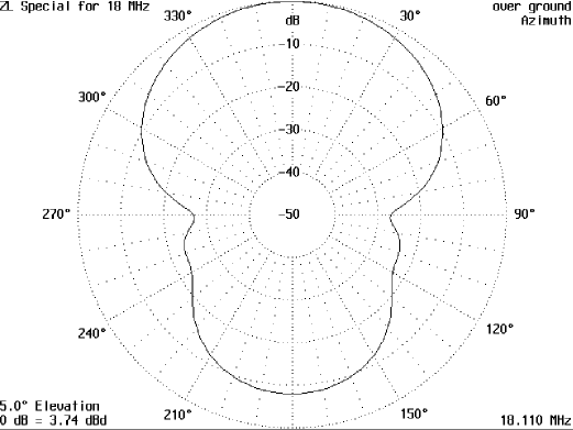
Looking at Figure 2 (below), this is the polar plot of the antenna. It does not have a very high front-to-back ratio, but this is not a disadvantage on this band as it does not seem to be very crowded. As a matter of fact, in a pileup when everyone is screaming at the DX station, this will enable you to know when the roar dies down to allow you to slip in a call. I found this to be an advantage when working into the South Pacific. Nearly everyone behind and to the east had to shoot over me. When they quit, I called the DX stations with good results. Even worked A35DX on Tonga through a HUGE pileup with 25 watts.
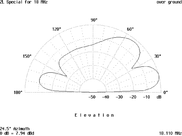
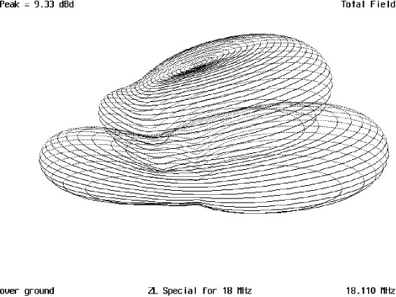
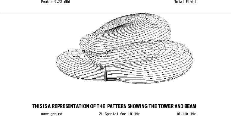
Continuing to Figure 3, this is the vertical pattern of the antenna. You will notice there are two lobes with the major lobe at 14 degrees and a secondary at approximately 50 degrees. This is a good thing because it allows a primary low angle DX first. Then, as conditions change the secondary lobe will allow you to keep working stations somewhat closer in. This is due to the higher radiation angle coming down closer than the primary angle at 14 degrees. This will go a lot further before coming back down due to the lower angle of radiation. Figure 4 is a 3D representation of the antenna pattern and Figure 5 is the same only with the tower and beam shown.
DIMENSIONS
Rear driven elements 12 ft, 11 ½” each
Front driven elements 12 ft, 11 1/8” each
Spacing 12 ft, 11 1/8”
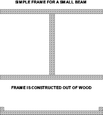
All the dimensions were calculated after many runs and were optimized at a 51ft. height. This is the same height as the standard 50ft TV push up mast plus a 1 ft mast sticking out of the rotor. This beam can be rotated by any TV rotator since it’s not very heavy if attention is paid to construction methods and materials. The use of 2” by 2” or 2” by 4” wood for the boom, properly weatherproofed, and 2” by 2” for the element supports, will enable the construction to be done cheaply, in most cases. By putting pieces of PVC around the elements and using electrical conduit clamps to secure the elements to the wooden supports, it will be insulated well enough for amateur power levels. Figure 6-6 shows a simple wooden frame for a simple beam.
The impedance comes to 73.3Ω + 30.9Ω for an SWR of 1:1.88 which any of the currently sold antenna couplers can handle if you want a flat line. A balun will help keep down the radiation from the feedline using either a coax-type or whatever you have on hand. If you do not have a balun, that is not going to make much difference in the long run, but it might keep the pattern from being skewered one way or the other.
Now, you have something to build, and with a beam on 17 meters you will make a loud hole in the band.
Originally posted on the AntennaX Online Magazine by Richard Morrow, K5CNF
Last Updated : 24th February 2024
