As I have mentioned before, I have my own small transmitting loop project under way and it is being built to operate on 30 through 12 meters. Following are a few of this loop’s construction photos. These are part of the total project and more will be taken as the project progresses. It is hoped these photos will give you the desire to build one of these antennas and then to see just how well they perform.
Loop Antenna Project Photo Tour - Photo 1
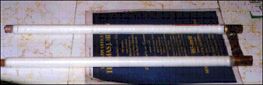
The two inner legs of the trombone capacitor are shown here and you can see the layers of the Teflon tape that have been wrapped on the ½ in. (1.27 Cm) pipe legs. The Teflon was then covered by 3 layers of clear shrink tubing to both protect the Teflon and to act as centering elements for the pipe. This method of insulation was chosen as it was far less expensive than using Lexan or polystyrene tubing for the insulation.. The use of the T junctions instead of the 90 degree elbows at the end was to allow the use of support rods in the original design, but that idea was dropped due to construction considerations. The ends of the capacitor have been sealed with RTV to prevent any possible arching.
Loop Antenna Project Photo Tour - Photo 2
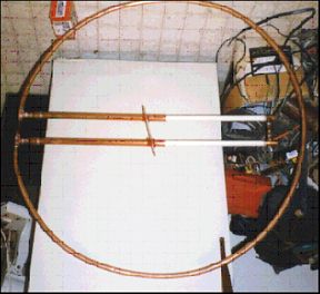
This is the loop with the capacitor legs partially installed into the loop. The lower Lexan brace is visible, and as shown, it is installed at an angle. This is to allow the lower ends of the outer part of the capacitor to be adjusted for spacing. This is to prevent the inner legs of the trombone from binding when it is being tuned.
Loop Antenna Project Photo Tour - Photo 3
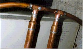
The upper gap of the loop is shown here with an insulating material, in this case phenolic, to keep the separation constant and for mechanical rigidity. The insulating material can be of any suitable material but such bracing should be used, particularly on large loops, as they will be more prone to twisting in the wind. In this case, the insulator is held in place by screws, however epoxy or other methods could be used.
Loop Antenna Project Photo Tour - Photo 4
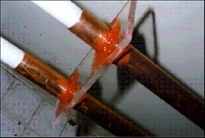
This shows the lower Lexan brace in more detail. The holes for the pipe were drilled oversized to allow the spacing to be adjusted. This is done by slanting the brace and twisting it slightly to change the separation of the ends of the pipes. When the correct separation was found, the RTV sealant was applied. The hole for the threaded adjusting rod has not been drilled yet. This is because the drive motor mounting method has not been determined at this time.
Well, this is as far as this particular loop project has progressed at this time and as more information becomes available, you will be able to get it here and only here.
Originally posted on the AntennaX Online Magazine by Richard Morrow, K5CNF