Off Center Fed Dipole
A lot has been said about keeping a dipole symmetrical about the feed point. It just ain’t necessary. Regardless of where you feed the dipole, the current distribution on the antenna does not change. That is just another way of saying that the maximum current will be in the center of the dipole, regardless of where you connect the feed line. Since the current distribution does not change, there is no change in the radiation pattern of the antenna, regardless of where you feed it. Incidentally, if it were fed at the end it would be called an end fed Zepp or the radiating element of a J-pole, which are both end fed 1/2 wave dipoles. If you can feed a dipole in the center or one end, why not somewhere else? That is the basis for this article.
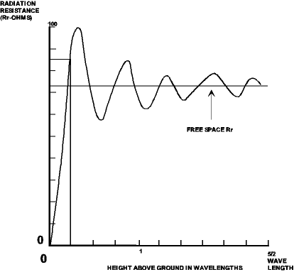
To show the change in feed point impedance versus position of the feed on the dipole, Figure 1 was plotted from calculations made on MININEC (an antenna analysis program). This was for a 1/2 wavelength dipole 1/4 wavelength above ground at 4 MHz. Note that you have to go a long way from the center to see much change. The computer program does not allow feeding at the end, but you can see how rapidly the impedance increases as you approach the end. Why is the impedance 84 ohms at the center? The height of a dipole determines the feed point impedance. (see Figure 2). By the way, the term impedance is correct, but at resonance the reactive component is zero, therefore the impedance consists of only the resistive components.
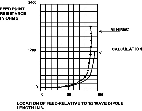
The current distribution on a 1/2 wavelength antenna approximates a cosine function. If you measure the impedance at the center of the dipole then divide that value by the cosine of the angle in electrical degrees from the center, you will get an approximation to the curve of Figure 1. In equation form, this says:
Z = ZF/COS(A)
where Z is the desired impedance, ZF is the impedance at the center of the antenna, and A is the angle in electrical degrees from the center of the antenna. If you manipulate this equation with algebra you get:
COS(A) = ZF/Z
Therefore, to determine the desired feed point location for an antenna, divide the feed point impedance measured at the center of the antenna by the desired feedpoint impedance, then take the arc cosine of that number and the result is the number of electrical degrees from the center of the antenna. There will be a slight error due to the fringing effects at the end of the dipole, which simply means that the current distribution is not exactly a true cosine function, but is sufficiently close for our purpose. The impedance based on a cosine calculation is plotted on Figure 1 for comparison.
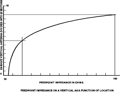
As another example of this concept, the same information applies to a vertical, which normally has a low feed point impedance. Figure 3 shows the impedance versus location on a 1/4 wave vertical for 80 meters.
A common problem with beam antennas, or other antennas that are close to a reflector, is a low value of feedpoint impedance. It is very difficult to build matching networks that keep the transmitter happy and not have loss in the matching network. In addition, they cost money. Why not move the feed away from center rather than build a matching network?
For an example, if we had a beam with 20 ohms at the center and wanted a match to 50Ω.
COS(A) = 20/50 = 0.4
ARC COS(0.4)=66.42 degrees
To convert that to feet, assume the length of the driven element of the beam = 32 feet, which is 180 electrical degrees (1/2 wavelength). That also says that there are 90 degrees from the center to one end. Therefore.
66.42/90 = 0.738
which is the fractional distance from the center of the element to one end. Now, 0.738*16 = 11.8 feet, which is the distance in feet from the center of the antenna for a feed point impedance of 50 ohms for your beam. Ain’t that slick?
If you have an antenna that has a very low feed point impedance, just change where you feed it to get the value you want. You can either use the equation or you could scale Figure 1 for 20Ω at the center then slide out on the curve to get a close estimate of where the feed ought to be. Seems to me that is a lot easier than trying to build a matching network to transform some low impedance to 50Ω.
This won’t work if you just plan to hook up the coax at the feed point. Never feed a dipole or any other balanced antenna without a balanced feed. Coax baluns are cheap and they really do make a difference. An unbalanced coax feed is like adding a wire (the outside conductor of the coax) to the antenna. Currents will flow on that wire and change the intended radiation pattern to something you had not planned on.
It is easy to write about theory, but there are always a number of considerations needed to translate theory to practice. This case is a perfect example. If you try to feed a dipole off center, even with a balun, the unbalance in the balun is enough to screw up the works. The only way I have been able to solve the problem is as follows: Run the coax up to the center of the antenna (which is the low impedance point). Connect the coax shield to the antenna at this point. Run the coax along the antenna wire to the desired feed point. For the remainder of the wire length, connect the wire to the center conductor of the coax. Since you don’t need that part of the wire that is parallel to the coax shield, remove it.
If you build a beam, run the coax inside the pipe, beginning at the center of the element. Put an insulator in the pipe at the desired feed point, and connect the center conductor to the short piece of the remaining element, and the coax shield to the long segment of the beam element.
In the case of the vertical (Figure 3), the coax could be run inside the vertical and no balun is necessary. Connect the braid of the coax to the lower portion and the center conductor to the top portion of the vertical. If you have a support, connect the coax braid to the ground plane. At the desired feed point, remove the coax braid and let the center conductor be the remainder of the vertical. Where you opened the braid is the output of the coax, which is a 50 ohm source. In this antenna, the coax braid is the lower portion of the antenna.
This is the type of information antenneX was designed to pass on. The fact that this one is not in the Antenna Handbooks simply means that none of the books cover everything about antennas. If they did, there wouldn’t be any fun left in thinking up new ways to bend wire to create an effective radiator. Hope this trick helps solve some of your problems.
Originally posted on the AntennaX Online Magazine by Ted Hart, W5QJR
Last Updated : 13th March 2024