The Half-Wave Vertical
The basic antenna for 20 meters is only about 31 ft. tall and will give good results for anyone who wants to work DX on the 20-meter band. It can be made to be function as a 40 meter 1/4 wave vertical as well, and will do a fair job without radials. The advantage of the 20-meter 1/2 wave vertical is it has a much lower angle of radiation than a 1/4 wave vertical.
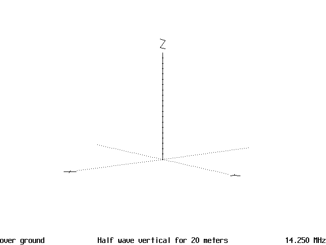
Figure 1 is the diagram of a half-wave 20-meter vertical and is 31 ft. tall. It is fed at the bottom and this is a high impedance feed point, so, some sort of impedance matching network is going to be required. Usually an L network will do the job very well. The only other requirement is to install a rf choke from the base of the antenna to ground to drain off static electricity. Both the L network and the rf choke need to be placed at the base of the antenna in a weather proof housing. In most cases the antenna will have a low SWR to cover the entire 20 meter band when tuned for the middle of the band and the network will not have to be adjusted after it is tuned up.

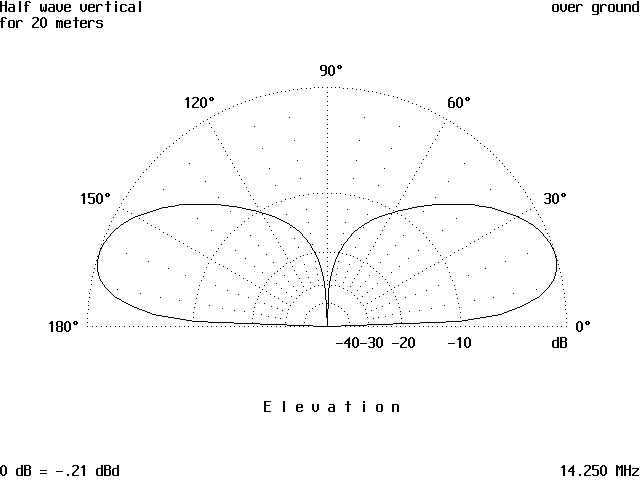
Figure 2 is the vertical radiation pattern of the antenna and you can see the angle of radiation is in the 15 to 20 degree range. This is what gives the antenna its good DX characteristics, a low angle of radiation.

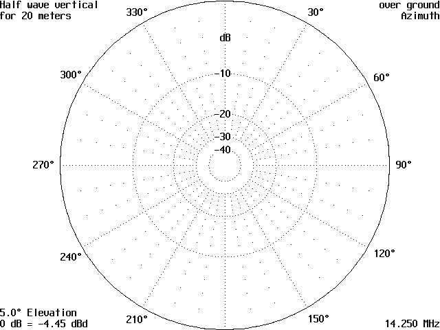
Figure 3 is the horizontal radiation pattern and is circular, which enables you to hear any place the band is open to at any particular time. Granted, this can be a disadvantage at times, but for the most part, it is no problem. At least you can hear when the pileup starts to calm down and can jump in and give a call.

This antenna does not have very much gain to speak of, but the angle of radiation is what makes the difference. A 1/4 wave vertical has a vertical angle of radiation that peaks out at 34-38 degrees and this means the first hop is a lot closer in than the lower angle of radiation that characterizes the 1/2 wave vertical. This enables the antenna to get out farther and sooner than the 1/4 wave vertical and keeps working the DX longer, as the band opens and closes.
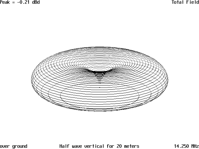
Figure 4 is the 3D pattern of the antenna and as you can see it is a lot flatter pattern. There is the usual null straight up over the antenna and the rest of the pattern shows the excellent concentration of radiated power at the lower angles.

Figure 5 shows the current distribution along the antenna, with the most current flowing in the center of the antenna and this is what gives the antenna a low angle of radiation. There is also less loss due to ground absorption, which means more signal will get in the air where we want it.
The 1/2 wave vertical is practical at frequencies above 14 MHz, as the total height becomes excessive at the lower frequencies, 65 ft. for 40 meters and 130 ft. for 75 meters. At the higher frequencies the antenna could be made self-supporting without too much trouble. Also, if you are operating on harmonically related frequencies such as 14 MHz and 28 MHz, the antenna can be made to function on two bands such as the 14 MHz antenna will work on 7.0 MHz by switching the matching network to match the antenna on 7 MHz. The 28 MHz can be done the same way and function on 14 MHz in the same manner. If there is a real desire to operate 3 bands, the 14 MHz can be used as a full wave vertical on 10 meters with good results. Switching the matching network is the only requirement to do this.
Originally posted on the AntennaX Online Magazine by Richard Morrow, K5CNF
Last Updated : 15th March 2024
