Last month in the November 2002 issue #67 of antenneX, I investigated the process of varying the inductive loading of a fixed-wire length monopole by adjusting the portion of the wire that was wound into the coil and following the change of resonant frequencies that resulted. This month I added an identical coil/wire system and made a dipole antenna with the two wires. Both sides of the dipole were unwound together a turn at a time and the resultant changes in resonant frequencies compared to the single wire case. Figure 1 shows the block diagram for both months’ tests.
New Response Observed
The same regime of two kinds of frequency change happens when a dipole is adjusted. Starting from a full coil, the lowest frequency that corresponds to the coil/wire combination acting as a quarter wave transformer from free space to the transmission line goes down as the coil is unwound and the freed wire is extended. A minimum frequency is approached that is lower than that reached with a monopole—it acts as if the total inductance is the sum of the two coils—and the minimum happens when a larger number of turns is removed. In addition, a high impedance resonant frequency appears at the frequency where the coil/wire combination on each side of the dipole acts like a half wave transformer. This new response also moves down and then back up in frequency as the unwinding continues. All other resonant frequencies move up monotonically as the coil shrinks. The average impedance and SWR at resonance is an indication of the character of each resonance; this calculation shows clearly that the second resonance is a different kind of response than the lowest frequency.
Un-winding the Coils - Figure 1
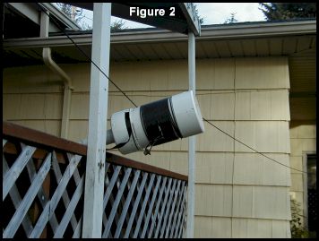
Un-winding the Coils - Figure 2
Figure 2 (and the header picture attached to analyzer) shows a view of the PVC pipe section with the coils of both sides of the dipole partially unwound. The position of the fixture on the deck allowed a test of all coil sizes from 28 turns down to 16 turns, while still having room to extend the unwound wire to its fullest extent using the pulley-string setup used last month. Table 1 reiterates the coil physical properties.
Un-winding the Coils - Table 1
Table 2 reiterates the monopole resonant frequencies as the coil is unwound. The first column is the turns left on the coil. All other columns are particular resonant frequency modes associated with the antenna. The purple header in Tables 2 and 3 show which series of resonant frequencies appear to be controlled by the coil/wire combination. The white header shows the resonant frequencies that are controlled by the shrinking inductance of the coil. The rust colored bar covering the turns and lowest frequency indicates the situation producing the maximum lowering of the frequency of the antenna by the coil.
Un-winding the Coils - Table 2
Table 3 shows the same situation for the dipole. Note that two frequencies show a minimum frequency point as indicated by the rust colored bar. They are only harmonically related at one coil size, however—at 20 turns (indicated by the light blue background). Two other strange things happen when a dipole is unwound: a resonant series at about 15 MHz only exists for the largest three numbers of turns on the coil; and a series that seems to be associated only with the extended wire (it drops in frequency as the wire extends longer and longer) crosses the next higher series at 24 MHz and 20 turns before continuing downward to 20 MHz. This series is shown in the dark blue background. Below each column in Table 3 are the separate average of the resistive and reactance parts from the impedance at each data point in the series, the impedance magnitude of that average and the average SWR for the series. The darker gray second frequency column shows that this resonant frequency is associated with a much higher impedance than the others. All of the “coil-alone” modes give a good match to the transmission line, but they may not be radiating.
Un-winding the Coils - Table 3
Un-winding the Coils - Table 4
Table 4 compares the lowest resonant frequencies of the monopole and dipole configurations. It is interesting that the number of coil turns where the second frequency is twice the lowest frequency in Table 3 is also a situation where the square of the monopole/dipole frequency ratio is also 2. The data on these two tables suggest that a particular size exists where an antenna can operate automatically on two bands without re-tuning.
Tables 5a and 5b show various physical and electrical characteristics that can be computed for each data point of the lowest and second lowest resonant frequency data series. The first column is the number of turns on the coil. The next three columns show the associated lengths of the extended wire in inches, meters, and wavelengths at the listed frequency. The frequency and its wavelength are shown in the next two (yellow) columns. The length in wavelengths of the whole wire is shown in the green column. The inductance of the coil is shown, with its associated reactance, in the 7th and 8th column, and the capacitance required to resonate that inductance at the listed frequency is in the last column. The light blue bar at 20 turns highlights the special harmonically related conditions mentioned above.
Un-winding the Coils - Table 5a
Un-winding the Coils - Table 5b
Substantial Shrinkage Achieved
This data shows that a substantial shrinkage of the resonant frequency can be achieved using the loading coils. An antenna length of 10.16 meters plus the coil size resonated at 2.38 MHz, just above the 160-meter band. It is also clear that a special set of sizes is needed for maximum shrinkage. Limited experiments to scale this data to 40 meters (80 and 160 meters at my location is too noisy to be useful) reminded me that the coil physical configuration sets the inductance, which in turn moves all the resonant frequencies around. The results above are for a coil diameter of 6 inches and a wound length of about 2 inches. A longer, smaller diameter coil would give higher inductance and might further increase the antenna shrinkage possible for a fixed length of wire in the coil.
The next step is to investigate the coil form factor effects and define the dimension ratios for maximum inductance while keeping within the limits set by the wavelengths of extended wire and wavelengths of total available wire shown in the tables above. The intent is to develop and understand a set of design rules for shrinking antennas with loading coils
Originally posted on the AntennaX Online Magazine by L. B. Cebik, W4RNL