The CFA Radiation
In last month’s article that appeared in the June 2000 issue of antenneX, I described a simple pi network with minimum lead length to feed the CFA. During this month I have been investigating this circuit’s relationships between E plate voltage, D plate voltage, Phase between these two voltages, and radiation as measured by a nearby field strength meter. I expected that the radiation would peak when the phase is at 90 degrees, and the current through the D plate is in phase with the E plate voltage. However, the most prominent requirement for radiation seems to be the E plate voltage! I also built a magnetic loop with a twist—literally. This is an attempt to make a H field generator, which when combined with an E field generator, might allow investigation of the field shape conditions involved in the CFA.
The E plate voltage was always relatively large and a clean sine wave, so I chose it to establish the period by recording the position (calibrated in the little hash marks along the horizontal axis of the scope screen) of the first and second downward sloping zero crossings. To do this accurately, the vertical position is used to locate the straight line displayed when the input is grounded (a switch on the scope allows a choice of AC coupling, DC coupling, or ground) at the horizontal scale location. Next, the E plate voltage is displayed by moving the switch to AC coupling, and the horizontal position is used to set the first zero crossing to a convenient mark. I chose 5 marks in from the edge.
This process shifts the whole trace for both D and E plate voltages horizontally under the graticle ruler. The horizontal mark where the second zero crossing goes past the ruler gives the end of the RF period. The D plate voltage is then located under the horizontal ruler the same way using its channel vertical position control – by first grounding the input to move the straight line, etc. without changing the horizontal position of the traces. The location horizontally of the first zero crossing of the D plate voltage, which is somewhere within the period of the E plate voltage, gives the phase. This procedure works for all amplitudes and vertical scale settings since all numbers are taken at zero volts. The D plate voltage tunes through a null with this circuit, and the phase can be observed to shift from almost exactly out of phase to almost exactly in phase as the frequency is moved through the null value. At the null, the voltage is small, and residual third and higher harmonics (which are not nulled out) make up most of the signal, distorting the waveform and changing the zero crossing. As a result, it is hard to find the frequency where the D plate to E plate voltage phase is exactly 90 degrees.
The field strength meter is essentially a crystal set with a high Q tuner. It had to be tuned each time the frequency was changed. I found great interaction between my position near the tuning knob and the reading on the meter, so I had to make a tuning wand out of a 3-foot (91cm) length of 1-inch (2.54cm) PVC pipe with slots cut in the end to fit the knob on the field strength meter. This eliminated a lot of variation in the measured field strength. The crystal set “phones” output allowed the detected 400-cycle modulation to be connected to the input of a HP400D AC milli-voltmeter to indicate field strength. About 5 percent modulation was applied to the RF waveform.
Figure 1 shows the tuner/CFA schematic.
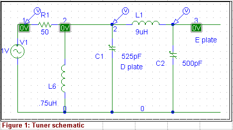
Figure 2 shows the simulation output in the frequency range near the operating frequency of 3.5 MHz.
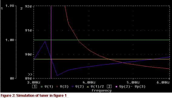
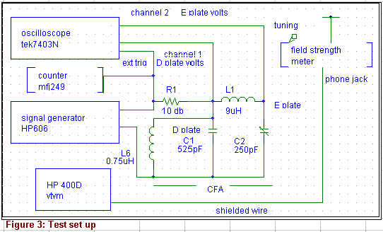
Figure 3 shows the block diagram of the test set up.
A typical set of steps to take all the data in the tables at a single frequency is:
Tune signal generator using the counter to indicate frequency
- Tune the field strength meter to the new frequency without moving its box
- Adjust the channel gains on the scope to put the whole waveform amplitude on the screen if necessary
- Using the vertical position control, set the bottom of the sine wave to the bottom of the screen
- Using the horizontal position control, move the top of the sine wave to the vertical scale and read the voltage
- Set the horizontal position as described above and measure the phases
- Record the field strength meter reading from the AC vtvm
Since the phase set up is mostly done – it might change slightly horizontally at the next frequency – the next frequency can be done in the reverse order: steps 1,2,7,6,3,4,5.
Tables 1 and 2 show the results for two CFA tuner conditions: with and without the small input inductor L6 in the schematic (Figure 1). The first 7 columns give the data as measured by the process described above. The 8th column gives the computed phase according to the formula:
Note that the D plate voltage is 180 degrees out of phase with the E plate above the null frequency and closely in phase with the E plate below the null frequency. The relative phase shifts rapidly through 90 degrees at the null.
The objective of all this is to compare the radiation as measured by the field strength meter with the phase and the voltages on the D and E plates. If the radiation peaks when the phase is 90 degrees, the antenna is behaving as advertised for the CFA. If it peaks when the E plate voltage peaks, it is behaving like a short extended capacitance or monopole. Only if it peaks when phase is 90 degrees and SWR is low and the E/D voltage ratio is correct will this thing be a CFA, according to the theory given by its inventors.
To try to see what is happening, I computed three “quality factors” from the data. The first is the ratio of field strength meter output to E plate voltage. At frequencies where this number is large and constant, it shows the band where E plate voltage is determining the radiation. The second is the ratio of field strength to phase. If it peaks at a frequency, the phase there is optimal. The third is the product of the first two, normalized to its highest value.
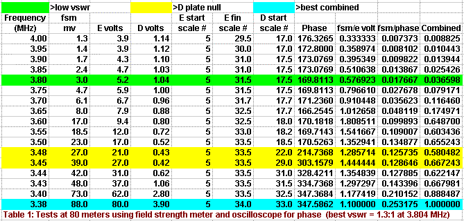
The network as simulated and described last month (shown in Figure 1) shows the following characteristics in Table 1:
- The matching relates to nothing except D plate voltage = 1.0. The low relative efficiency at the best match is shown by the combined quality factor of 3%. No wonder it doesn’t radiate!!
- The E plate voltage alone is a strong, roughly constant factor centered on the null frequency.
- The quality number for phase between D and E plates is at maximum when the voltages are in phase and is only half as good at 90 degrees.
The best radiation is where the E plate voltage peaks (3.37 MHz) and the D and E plate voltages are in phase. This setup is not a CFA!
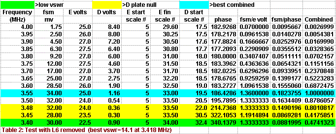
Removing the small inductor that helped the matching looks more hopeful. Table 2 shows:
- The best frequency for all quality factors is 3.55 MHz. This is just above the null frequency.
- The E plate voltage is a strong factor when the frequency is near and below the null frequency, where D voltage to E voltage phase is changing or the voltages are in phase.
- The best phase is 180 degrees just before the shift begins at the null.
- The vswr at 3.55 MHz is high even though the D plate voltage is near 1 because the unit looks reactive at that frequency.
- Another way to get rid of the reactance might bring all the best factors together, but I still do not see peaking at 90 degrees phase.
Since I see no effect of displacement current in the D plate capacitor, which sets the 90 degrees requirement on the D plate voltage, I must conclude this antenna is not behaving as advertised. This CFA differs from the others in that it has a high capacitance D plate with small spacing and a Lucite dielectric. To eliminate this factor these experiments will be repeated with more a conventional, low capacitance air dielectric.
These experiments show some reasons why it is so hard to sort out the CFA parameters. Clearly, as I have said before, matching is not equal to radiation!!! I found considerable interaction with the surroundings with this setup, and had to be careful to always sit in the same position among the equipment to get stable readings. The frequency just above that where the phase starts changing seems to be some kind of important point. It is easy to make a “radiator” that is just a high voltage extended capacitor. Displacement current may not be the way to generate an H field. And, finally, it may not really work by combining fields at all!!!
To more efficiently test the field combination theory, I have started along the idea of building an E field generator (a small capacitor) and a magnetic loop. In an attempt to isolate just one side of the loop, I built a twisted loop – where the leg opposite the desired radiator is twisted to a polarization 90 degrees from the H field generator. If successful in getting a clear H field generator, then the two can be moved around to see if some field configuration radiates. I would welcome any comments on this approach, and also any further insights determined by others from the data in Tables 1 and 2.
Originally posted on the AntennaX Online Magazine by Joel C. Hungerford, KB1EGI
Last Updated : 29th May 2024
