The Inductance Neutralized
Yes it is possible with the combination of transistors and coax cable to neutralize the inductance in a loop antenna and couple current into a broadband circuit at low (less than 0.3 ohms) impedance. When I say broadband I mean over at least a 10 to 1 frequency range. Remember this is a receiving antenna and I make no claim about it being a transmitting antenna. In fact the patent examiner claimed it would not work as a receiving antenna because it could not operate as a transmitting antenna and would break the law of reciprocity if it could operate as a receiving antenna. The company I was working for at the time was not interested in transmitting antennas so we never examined it as a transmitting antenna.
Patent Obtained
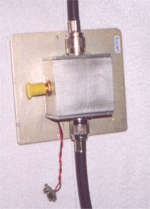
In the late 1960s the patent office had to belive that an invention would in fact work before they would grant a patent so they suggested we have an independent laboratory test and confirm that the invention did indeed function as claimed. The patent office does not have to understand why a device functions, only that it functions as claimed. The company then contracted an independent laboratory to perform the testing which confirmed the operation of the antenna and the patent was granted in 1972 as US Patent 03774218.
Bear with me while I tell the story of how and why the antenna was invented and then I will get down to explaining how and why I think the antenna works.
In the 1960s, after serving four years in the Air Force, I went to work for a company developing electronic warfare equipment for the war effort. We were developing broadband direction finding equipment and needed an antenna that would cover 2 MHz to 70 MHz while maintaining phase tracking between two antennas of better than 2 degrees over that frequency range. The antenna needed to have good sensitivity and be as small as possible. If you approach the problem in the conventional way of dealing with the inductance by tuning it out with capacitors, the antenna would get to be very complex and nearly impossible to maintain phase tracking over the frequency range. I was a junior engineer at the time and not assigned to the problem but I was aware of it and began working on it in my radio shack at home. I thought I would make an impression on those senior engineers if I could solve the problem. After all, I had bought a 15 MHz Heath Kit oscilloscope and HF receiver-what else do you need?
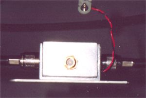
As a result, I managed to figure out how to neutralize the inductance in a loop antenna and the company went on to sell several million dollars worth of systems based on the antenna. I got a $300.00 bonus and earned some respect as well. After leaving that company for a really big pay raise and a chance to live in Austin, Texas USA instead of Dallas, I went to work for a large aerospace company. I was there for the next 19 years mainly deigning radios, telemetry, OMEGA, LORAN and GPS. Along the way I invented a low noise method of spreading the bandwidth of a ferrite loop antenna which gave the company a leg up on the competition in commercial aviation OMEGA (10KHz to 20 KHz) navigation receivers by being smaller in size than any other antenna in use. That company got in trouble in the late 1980s and sold the navigation division. This fateful event caused three people and myself to form a new company. That company is now working on $10 million a year in DGPS sales.

After discovering antenneX on the Internet about a year ago I decided it would be a good idea to tell some people that may be interested and could understand the implications of the antenna. The patent has expired and I never owned it anyway so I would hope some of you would experiment with it and find uses for it.
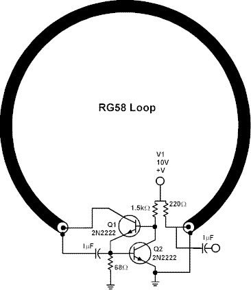
The circuit is shown in Figure 1 is the same circuit that was patented. Neutralizing the inductance of the loop was thought to be possible because I knew low inductance wire wound resistors were made by arranging the circuit to have two wires wound close together so that currents would flow in opposite directions through the two wires. Another hint was that transformers appear to neutralize the inductance in the primary when the secondary is loaded. Why else would a shorted secondary reflect such low impedance in the primary when it is known that a well designed transformer has an inductive reactance of at least five times the load resistance it is designed to support?
How it was Invented
I think the best way to explain how the antenna circuit works is to go through my thought process when it was invented. Let’s assume when a radio wave is passing by, it is trying to induce a current in the shield and center conductor of the coax. The current induced in the shield is allowed to flow because it sees low impedance when it encounters the emitter of the transistor Q1. The current attempting to be induced in the coax center conductor is inhibited from flowing because it encounters high impedance when it sees the collector of Q1. In fact the collector of a transistor looks like a current source at low frequencies (HF), which means the current is independent of the voltage on the collector. However, the current being accepted at the emitter is going out the collector and is forced to flow in the opposite physical direction as that in the emitter. When we have these conditions we then see the magic of forcing the current back through the center conductor. The inductance is neutralized and yet more current can flow in the emitter. In fact, with this circuit and a 2 foot diameter loop, one will see about 30-dB difference in gain when you connect the circuit so that Q1’s collector is connected directly to the output and not allowed to flow through the center conductor.
The Circuit Details
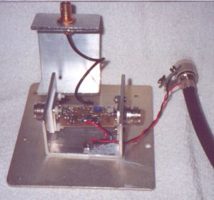
Let’s explain the transistor circuit in a little more detail. Q1 is a common base stage with an input impedance of about 3 ohms if the base is bypassed to ground. The impedance at the emitter of a transistor is about 30 ohms divided by the emitter current in mA. The current in Q1 is set to about 10 mA so the impedance is 3 ohms before we consider the effects of Q2. Q2 amplifies any voltage at the base of Q1 and feeds it back to Q1’s base 180 degrees out of phase. This has the effect of lowering the input impedance by the gain of Q2. Then, if we consider the gain of Q2 to be at least 10 in the HF band, the input impedance will be 3/10 (or about 0.3 ohms) for this circuit.
The circuit is self-biasing at about 0.6 volts across the emitter resistor of Q2. It works like this: at power-up, the resistor at the base of Q1 turns Q1 on and cause the voltage to rise across the emitter resistor until Q2 is turned on. This drops the voltage on the base of Q1 to about 1.2 volts. So the circuit is somewhat independent of the supply voltage and may be operated over 5 to 24 volts.
If you build the circuit and are within 20 miles of local broadcast stations, you will see volts of signal, which in fact is a problem for most receivers because it causes cross-modulation. The antenna exhibits good sensitivity to 15 or 20 MHz where the collector capacitance begins to shunt the neutralization current and the gain begins to fall off. It should be noted that if the load is 50 ohms on the circuit output, the collector of Q1will see 50 ohms without any reactance due to the cable. The transistor’s collector simply sees a properly terminated coax, which is seen as a 50-ohm resistor. This may not be the correct explanation of how the circuit works but it is the way I thought of it when it was invented. Other ways of looking at the circuit might yield a better understanding.
The circuit can be thought of as a magnetic field sensor with a feedback that causes the sensor to be invisible to the field it is sensing. For example you can run the coax through two toroids with coils that have signals injected into the coils on the toroids and the signals will appear on the output of the circuit. However, if you inject a signal in only one of the coils the signal will not appear in the other toroid coil, as would be the case if it were a shorted turn. This effect can be used to sum signals with isolation or, for example, place two ferrite rods tuned at different frequencies and see both signals in the output. So in effect the shorted turn is appearing to the external world as an open turn without current flow yet the fields are sensed as if it was a shorted turn.
Explain This
There is an experiment I performed and the results of which I do not understand. I measured the input impedance of the circuit by feeding the input through a 50-ohm resistor. While shunting the input with a resistor of 0.5 ohms, I saw a drop of less than 6 dB in the output. This means the input impedance is close to the predicted 0.3 ohms. However, if I connect the same resistor while receiving a signal from the loop, I see a much larger than 6 dB drop in signal at the output. The only explanation that comes to my mind is that the radiation impedance of the loop is much higher than expected because of the feedback circuit. If this were true there might be hope for some type of feedback circuit to allow the technique to be used as a transmitting antenna because the problem with short antennas as radiators is low radiation impedance. This may be my personal contribution in part perhaps toward the search for a compact transmitting antenna?
I would like for the experimenters to build and test some of these types of circuits. Then discover and perhaps see for yourself what I think is a phenomenon of near magical proportion-how the circuit amplifies radiated waves while exhibiting such a broad bandwidth!
Editors Comments
The loop described above was tested here at the antenneX office building in the parking lot under far less than ideal conditions. It preformed as described in the specifications for the loop. The parking lot is in the back of a large Shopping Center, and is surrounded by several office buildings and power lines. There is a high degree of noise from air conditioners and many other pieces of electrical equipment to include an unknown by large number of computers. Within three miles (4.8 km) there is a broadcast station and a cellular TX/RX site (150-feet tall) is immediately behind the parking lot at a distance of about 300 feet. Not really the best place to test a loop but the only place immediately available. On the other hand, having the noise to deal with put the antenna to a more stringent test as far as rejection of such noise and interference is concerned.
The loop was suspended from a tree branch about four feet above the ground and my SGC-2020 was used for the receiver. Approximately 20 feet of RG-58U cable was used to connect the loop to the SGC. A 9-volt battery powered the loop amplifier.
Construction Details
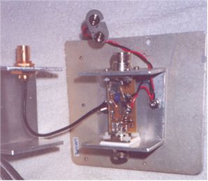
The loop is made of a length of RG-214/U cable and is a little over 2 feet in diameter. The amplifier assembly is in a sturdy aluminum case with a connector for a standard 9-volt battery on a short length of wire leading out of the case. There is a gold plated BNC connector for the connection to the loop and it is a very high quality connector. Inside the case is the amplifier assembly and it is mounted to the case with nylon insulators. All components are SMA, and of course, very tiny. This antenna is not for outside installation in this current configuration as none of the components are weather proofed. For installation in an attic or other indoor location, a frame (like PVC) would need to be constructed to hold the loop in a rigid circular shape. Of course the device shown in this article is a prototype version for testing purposes.
Results
In the range from 1.8 to 22 MHz, the signals were all readable and there was considerable reduction of noise as compared to a mobile antenna installation resonant on each band of operation. Sometimes the signals not heard on the vertical whip and were heard on the loop. The wind also blew the antenna around some and this demonstrated the figure 8 signal pattern of the loop quite well. I was listening to WWV at the time and the signal would fade in and out as the antenna rotated in the wind. The noise level was considerably reduced with the loop as compared to the mobile antenna on all the WWV signals listened to.
Listening to the SW broadcast signals resulted in clearer signals than could be received with the center-loaded and matched whip. I did notice that the signal levels were down a little as compared to the whip, but the reduction of the noise made the signals all more readable despite the slightly lower receive levels.
All things considered, the loop does what it was supposed to quite well and did an excellent job of rejecting the electrostatic noise component of the high noise level and amplifying the electromagnetic component of the signal quite well along with the small amount of electromagnetic noise component. As can be expected the desired signal won out over the little amount of undesired noise and was a lot more readable with the loop than when the whip was used for reception. For those who do not know, the loop antennas are more sensitive to electromagnetic signals than to electrostatic signals. Each transmitted signal has both elements, but noise consists of far more electrostatic energy than electromagnetic. So since the loop antennas are better at reception of the electromagnetic component, they tend to ignore the noise better than any other antenna.
This is a very interesting antenna and if used for a SWL antenna, the use of a rotor with an attic installation would allow the antenna to be rotated for maximum signal strength. The noise rejection is very good and for a location with a difficult environment for an antenna, this would be a good choice. Also, if the author’s thoughts about its potential as a transmitting loop can be made to work, then perhaps the best of both worlds can be realized!
Originally posted on the AntennaX Online Magazine by Clarence “Walt” Fowler, KC5ZDX
Last Updated : 29th May 2024
