Drake R-8 Receiver's (R-8, R-8A, R-8B and R-8B)
The R.L. Drake Company has been a leading name in American electronic communications since 1943.
The Drake R-8 is a microprocessor controlled, synthesized, all-mode, world band receiver offering excellent sensitivity, high dynamic range and other features for the most demanding listener. It has been designed as a “complete package.”
You get many items as standard-equipment, that would be extra on other receivers.
Multi-mode reception (AM, FM, USB, LSB, RTTY and CW) is featured throughout the range of the receiver (100 kHz to 30 MHz). A high-Q, 8-pole, electronically switched IF filter provides a range of five bandwidths. Later “firmware” permits user selection of bandwidths independent of mode and 100 Hz readout in AM (in later production only).
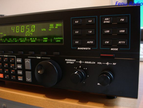
The front panel liquid crystal display provides visual feedback to the operator of the current status of the receiver. In the AM mode, a selectable synchronous detector (SYNCHRO) allows for enhanced reception by eliminating or reducing distortion due to fading signals.
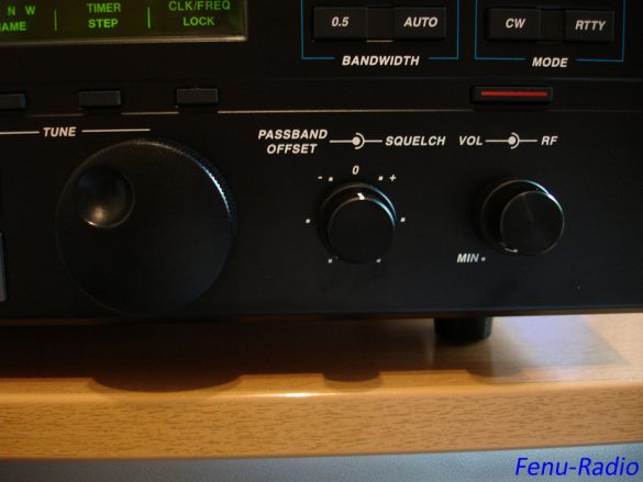
A Passband Offset control also aids in reducing or eliminating interfering signals by electronically shifting the receiver’s IF frequencies without disturbing the operating frequency. This action allows the operator to electronically move interfering signals out of the receiver’s passband thus utilizing the degree of selectivity provided by the high-Q, 8-pole IF filter.
The Passband Offset is also coupled to the synchronous detector (SYNCHRO) allowing the passband to be altered while the detector is in use. Other reception aids include selectable AGC, wide/narrow noise blanker, RF preamplifier for enhancing weak signals, RF attenuator for further improvement of strong signal handling capabilities and an adjustable RF gain.
A Notch filter is also supplied as an effective tool to eliminate offending tones (heterodynes). A muting control allows operation with a transmitter or transceiver.
The R-8 provides exceptional audio to the built-in speaker.
Two VFOs (tuners) called A and B, are provided on the R-8.
Selection is made with the VFO function key.
Frequencies can be directly entered through the keypad.
A programmable memory area allows for 100 non-volatile memories segmented into blocks of ten.
The following may be stored in any memory location: frequency, mode, bandwidth, AGC setting, RF setting, antenna, notch on/off, noise blanker setting and synchronous detector on/off.
As a result of three scan methods and three scan modes; nine distinct scan functions are supported in the R-8.
The three methods are: Stop at carrier detect, pause 5 seconds on carrier and pause at carrier until carrier drops for 5 seconds, then resume scan. The three modes are: Scan all memories, all unlocked memories of user-selected list or Scan from VFO A to B.
A built-in 24-hour clock-timer allows the R8 to turn on and off at pre-set times.
In addition, the rear panel Timer connection (5 pin DIN), allows control of small recorders, etc. to record a favourite program.
The R8 rear panel provides a common DB-9 connector for standard RS-232C data communications with a terminal or personal computer (9600,1,7,1,even).
This interface provides control and programming capability of the R-8.
Only the analogue controls such as volume, RF gain, etc. are not controllable.
There is also antenna inputs for coaxial lead in for wire type antennas.
A variety of AC input voltages may be selected as well as 12 VDC input.
The R-8 is a worthy successor to the earlier Drake R-7A.
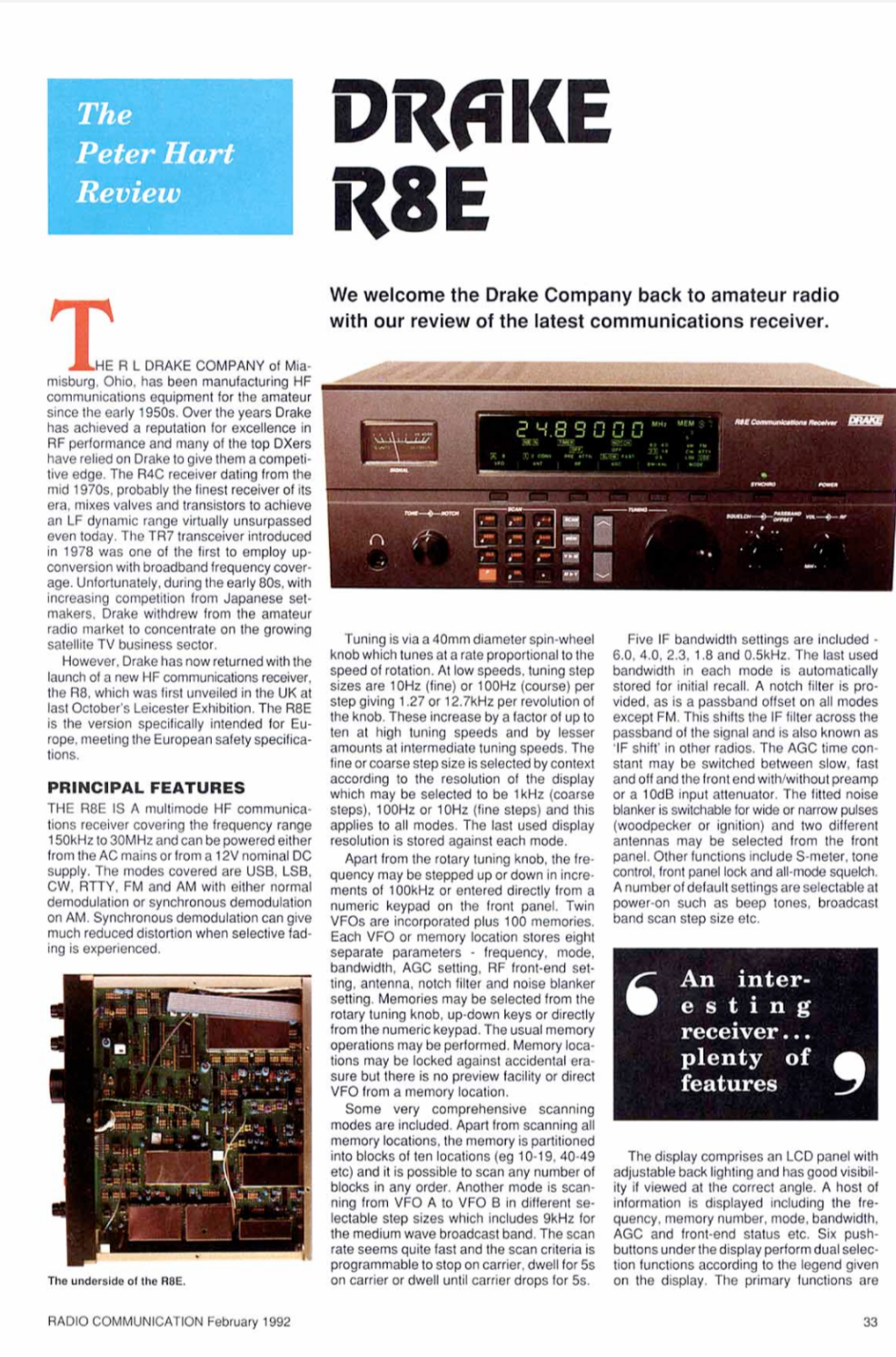
The Drake R-8E is the European Version of the R-8, with coverage down to 150 kHz per German law.
Frequency Range ...... 10 - 30000 kHz
AC Power ............. 100/120/200/240 VAC
                       50 or 60 Hz  40 Watts
DC Power ............. 11 - 16 VDC @ 2 Amps
Antenna 1, Converter   50 ohms unbalanced
Antenna 2 ............ 50 or 500 ohms unbal.
Selectivity ..........  @ -6dB     @ -60dB
   All modes except FM        6.0 kHz  < 12.0 kHz
                        4.0 kHz   < 8.0 kHz
                        2.3 kHz   < 4.5 kHz
                        1.8 kHz   < 3.6 kHz
                         .5 kHz   < 1.5 kHz
   FM mode only            12.0 kHz  < 25.0 kHz
Ultimate Selectivity   > 95 dB
Image Rejection ...... > 60 dB   .1-1.5 MHz
                       > 80 dB   1.5-30 MHz
I.F. Rejection ....... > 80 dB       45 MHz
                       > 100 dB      50 kHz
Third Ord. Intercept   > +20dBm
Dynamic Range ........ 100 dB
Notch Filter Attn. ... 40 dB min Depth (500-5000 Hz)
Sensitivity .......... 10 dB S+ N/N
   SSB/CW                < 1.0µV   .1-1.5 MHz
                       < 0.5µV   1.5-30 MHz
                       < 0.25µV    5-30 MHz1
   AM                   < 3.0µV   .1-1.5 MHz
                       < 1.5µV   1.5-30 MHz
                       < 0.8µV     5-30 MHz1
				    1 with preamp
   FM (12dB sinad)         < 0.5µV   1.5-30 MHz
Freq. Stability ...... ± 10 ppm. -10° to 50° C.
Freq. Accuracy ....... ± 100 Hz. -10° to 50° C.
Intermediate Freqs. .. 1st IF = 45 MHz
                       2nd IF = 50 kHz
Ext. Speaker Output .. 2.5 Watts, 4 Ohms.
                       < 10% distortion
Recorder Output ...... 300 mV, 4.7K Ohms.
Demodulator Output ... 300 mV, 4.7K Ohms.
Operating Temp. ...... -10° to 50° C.
Dimensions ........... 13.2W x 5.25H x 13D inches (334x134x330mm)
Weight ............... 13 lbs.(6 kg)  (16 lbs. ship)
|
Drake R-8, R-8A, and R-8B – Differences:
There are 3 versions of the R-8: the original R-8 along with A and B versions.
The R-8A introduced better front panel ergonomics (easier switching of mode and bandwidth).
The R-8B has more memories and has the best sync detector of the group (selectable AM sideband during sync).
The original R-8 uses an optical encoder with metal knob for tuning.
Later models use mechanical encoders with a plastic knob.
A VHF converter (not for broadcast FM) was available for internal installation in all models.
I have the straight R-8 and having to step through the filters sequentially is annoying but only a very minor annoyance.
The original R-8 uses an optical, rather than mechanical, encoder which is very reliable, and it has a heavier metal tuning knob rather than the plastic type used with the mechanical encoder on the more recent receivers.
The main advantage IMHO to the R-8B is the improved synchronous detector.
The R-8B has improved IM performance.
In the R-8B (as in the R-8 and R-8A), there is no frequency readout compensation for the offset required to resolve data signals. For example, to receive a fax signal on 8080 kHz one must tune in the USB mode to 8078.1kHz.
The utility listener will have to apply offset values to tune digital signals. The frequency readout on the green LCD panel displays an audio frequency, not the nominal carrier frequency listed in utility station guides.
For RTTY, the difference is the mark tone of 2125 kHz. For CW, 700 or 800 Hz. For fax (tuned in the USB mode), 1.9 kHz.
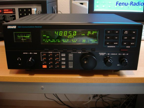
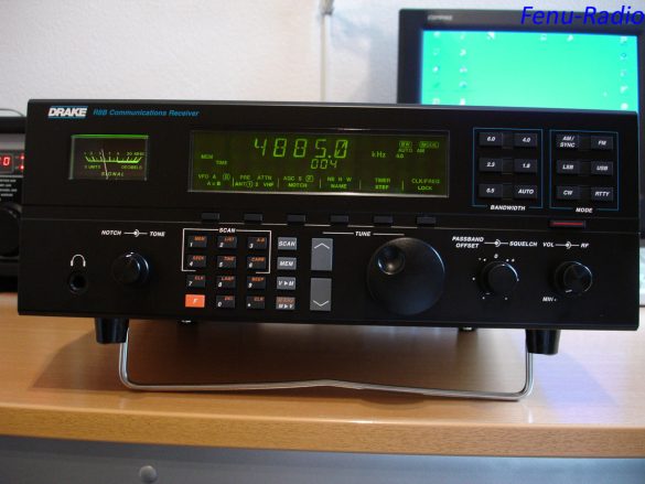
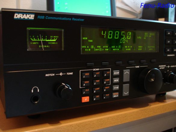
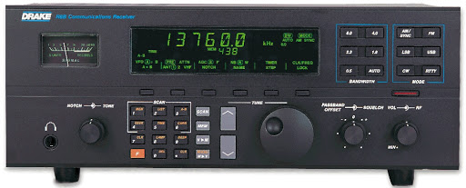
Photos of the Drake R-8B Receiver
Random Information I have come across on the Net.
Just a couple of repeated questions:
-
Is it true that later versions of the R-8B tune down to 10 KHz?
-
Yes the newer R-8B’s came with a revised ROM chip that allows the CPU to tune down to 10 Khz. However, the front-end of the receiver doesn’t have a dedicated bandpass filter (BPF) for the VLF range. There is considerable attenuation below 100 Khz because of this and performance is not what it could be.
-
How do I find out when my Drake R-8B was made?
-
The first digit in the serial number represents the year, 9 = 1999, 0 = 2000, 1 = 2001, etc. The second digit is a letter and represents the month, A = January, B = February, C = March, etc. The next four letters represent the model number. The last four digits are the unique serial number of that particular unit.
Yes the newer R-8B’s came with a revised ROM chip that allows the CPU to tune down to 10 Khz. However, the front-end of the receiver doesn’t have a dedicated bandpass filter (BPF) for the VLF range. There is considerable attenuation below 100 Khz because of this and performance is not what it could be.
The first digit in the serial number represents the year, 9 = 1999, 0 = 2000, 1 = 2001, etc. The second digit is a letter and represents the month, A = January, B = February, C = March, etc. The next four letters represent the model number. The last four digits are the unique serial number of that particular unit.
R-8B Backlight Modifications
Here’s a description of the R-8B “backlight mod” that I did using four bright white LED’s.
- Remove the Front panel knobs (set screws). The original R-8 uses a set screw on the metal tuning knob. The R-8A & R-8B models tuning knobs are plastic and pull off. It can be hard to do if it’s never been off before.
- Remove Front panel (black) with clear display window. (screws on top & bottom of panel).
- Remove Metal panel that holds two keypad membranes in place on their contact boards. (several screws) Set the keypads aside.
- Remove Front chassis frame from main frame. (two screws on each end) Pull the front chassis forward from the main frame for better access. Don’t stretch the connecting wires too much.
- Remove Multi-wire (blue) connector from the back side of the LED PCB. (PCB means Printed Circuit Board)
- Remove LCD display mounting screws on front chassis. (four screws, two on each end of the LCD) This is why you had to remove the metal frame that covers the keypad membranes. The two LCD screws on the right are not accessible with the keypad frame in place. If you want to make it easier to remove these LCD screws again, cut two semi-circular notches in the keypad frame where it covers the two LCD screw heads. I did it with my “Dremel” tool using a metal milling bit. You won’t have to remove the keypad frame again to access the right pair of LCD mounting screws.
Carefully remove the LCD with the LED backlight PCB still attached, from the front chassis frame. There may be a screw near the S-meter to remove.
7. Remove Six screws that hold the LED-PCB to the off/white plastic LCD frame. Keep your fingers clean so you don’t contaminate the contacts on the LCD side of the LED-PCB.
You now have the LCD assembly with it’s rear plastic frame ready to install the white LED’s. I used part # 900-7863 from the “Radio Shack.com” catalog. These are bright white 3-mm dia./ 4.0-V/ 20-ma/LED’s. You need four of them at US$3.49 ea.
I installed two white LED’s in each end of the LCD plastic frame. Space each pair about 1.5-cm apart and a few “mm” above the rear surface of the LCD. Drill the appropriate size holes for a snug fit so they won’t move around in the frame. The LCD plastic frame material is quite soft. Don’t push the LED’s too far into their holes. If they protrude on the inner surface of the frame, it might make the light uneven behind the LCD. I had to reposition two of them to eliminate a “spotlight” effect. Make sure you don’t lose the piece of white cloth material behind the LCD. It’s there to diffuse the backlighting.
Now you have to decide on how to power the white LED’s. I used the 5.0-V DC supply line on the LED board that can be tapped at pin #12 of the blue connector that you removed from the rear of the LED-PCB. If you use a 5.0-V source with the white LED’s that I used, it will require a current limiting resistor of about 150 ohms in series with one lead of each LED. The remaining leads must go to a ground point on the PCB. The disadvantage of using pin-12 on the LED PCB is that it’s always powered, even when the receiver is off, so the backlight is always on. I got around this by installing a small 12.0-V relay to control the 5.0-V line. The relay is powered by the 11-16V *switched* source from the power supply. Since this voltage source is turned off by another factory installed relay on the power supply PCB, the 5.0-V line to the white LED’s will be turned off by the relay I added. There are other possibilities for powering the white LED’s, including using the 11-16V source mentioned above. There is also a 10.0-V switched source available at the power supply. Either of these sources will require larger value current limiting resistors to keep the voltage/current within specs for the LED’s. Ohms law at work!
Using white LED’s will produce a display with white characters on a blue-green background. The blue-green colour is apparently intrinsic to the physical structure of the LCD material. It may also pick up a little green from the PCB behind it. I find the new backlight more pleasing than the “drab” OEM green. I think the characters have better definition too. You could experiment with putting a colour filter in front of the LCD or try bright blue, red or orange LED’s too.
Of course, you have to turn off the original green LED’s on the backlight PCB. I simply clipped them off the board with a snipper tool. If that sounds too “final” for you, you’ll have to get into the schematic to figure out how to remove the power from the green display LED’s (56 of them) without losing the six behind the S-meter. I decided it wasn’t worth the effort. I also think the white backlighting works better if the green ones are removed.
Their presence might add some green to the white light. I left the six behind the S-meter. Actually, I had already changed those six to regular yellow LED’s a while ago.
Be careful when reinstalling the backlight PCB to the rear of the LCD frame that you keep the (many) LCD control contacts clean. This is important so all the character segments of the LCD will work properly. I cleaned the contacts on the PCB with some alcohol just to be sure. You should also be careful not to contaminate the two “Zebra” strips that are embedded in the rear edges of the LCD frame where it makes contact with the LED-PCB. The strips look like a sandwiched layer of black between two pink layers. The material is spongy. These strips transfer the control signals between the PCB contacts and the rear of the LCD. After reading the above, I can imagine that some of you may be thinking I have too much time on my hands! I’ve always enjoyed “improving” my receivers over the years. It started with a Hallicrafters S20-R. When I got done with it, the circuitry was unrecognizable from the original design but the performance was greatly improved. I bought another S20-R for parts so I could restore the first to OEM condition. I guess it raises the question of how much you can change a receiver and still have the original item.
This article was written by J. W. Schermerhorn.
Keypad buttons on my R-8A don’t work well. Any suggestions?
To change or clean the keypad button assemblies, you have to remove all the front knobs and then the outer front (black) panel. This will expose the inner front panel frame. Each area of buttons is a rubber membrane which is held in place by a metal frame with screws around it. Remove each frame and take out the key membranes. Wash them carefully with a “soft” brush (no abrasives) in distilled water with a little liquid detergent. Be sure to clean/brush the electrical contact area on the backside of each key button. Rinse the membranes in distilled water several times and let them air dry.
While you have the key membranes removed, you should clean the gold colored contact traces on the printed circuit boards where each key touches them. Use some 91% isopropyl alcohol on a “Q” tip swab. Don’t rub the contact traces too hard.
This is a project you can do if you’re confident about working on electronic equipment, otherwise let Drake do it. The Drake part number for the 31-button key membrane kit is 2055191
Can my Drake R8A/B Tuning knob be improved? It’s too light!
The knob can be removed by pulling it towards you firmly. Some ways of making it heavier include the following.
Fill the hollow back of the R8A/B knob with a mixture of epoxy (slow curing) and steel ball bearing’s. It creates a smoother feel because of the increased mass/momentum. This doesn’t put any significant stress on the rotary encoder because it’s supported at the rear (behind the encoder wheel) in addition to the shaft in front. I haven’t noticed any wear/looseness since I weighted the knob several years ago.
Another suggestion includes using the tuning knob from an Icom IC-R72 which apparently fits very well and is ideally weighted.
The frequency hops/jumps on my R8B when using Main Tuning knob! Is there a fix for this?
The problem is very likely the tuning encoder wheel which is on the opposite end of the tuning knob shaft inside the front panel. The only reliable way to fix this is to replace the encoder. It is possible to clean it with some electronic spray like “DeOxIt” but it’s very difficult to get the spray inside the encoder without taking it apart and (you guessed it) it’s not made to be disassembled.
It’s also possible that the contact “fingers” of the encoder wheel assembly have become misaligned. In that case cleaning won’t correct the problem. You can order just the encoder wheel assembly without it’s PC board, which is not really needed. The part # is 3260012. It costs about $US12.00. Contact the Drake service department for it. Installing the new encoder assembly is not too difficult if you know how to solder well and are not timid about removing the covers and front panel of the radio.
It begins with removing all of the front panel knobs. The small ones have set screws. The big tuning knob pulls off. Remove the top and bottom covers of the radio along with the front (black) panel. This exposes the inner front chassis panel. Unscrew the hex nut that holds the tuning shaft/encoder assembly to the front chassis. This will allow you to remove the encoder with it’s PC board from the rear of the front chassis. You must also unplug the three wire connector that runs from the encoder PC board to one of the radio’s main PC boards.
Now you’re ready to prepare the new encoder for installation. Since you’re not going to use the old encoder PC board, you must unsolder the three wires from that board and resolder them to the three matching terminals of the new encoder assembly which doesn’t have a PC board. Put the new encoder shaft through the front chassis hole where the old one was and secure it with the hex nut. Plug the encoder wiring connector back on the main PC board. Reinstall the front (black) panel, top and bottom covers and all the knobs.
Downloads
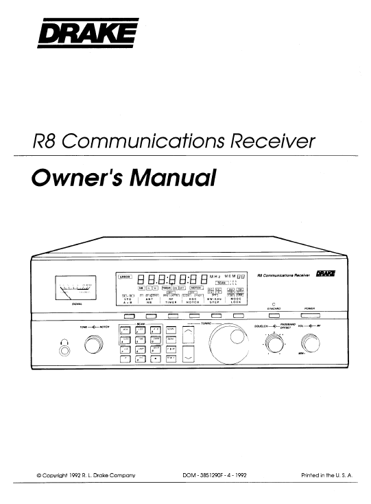
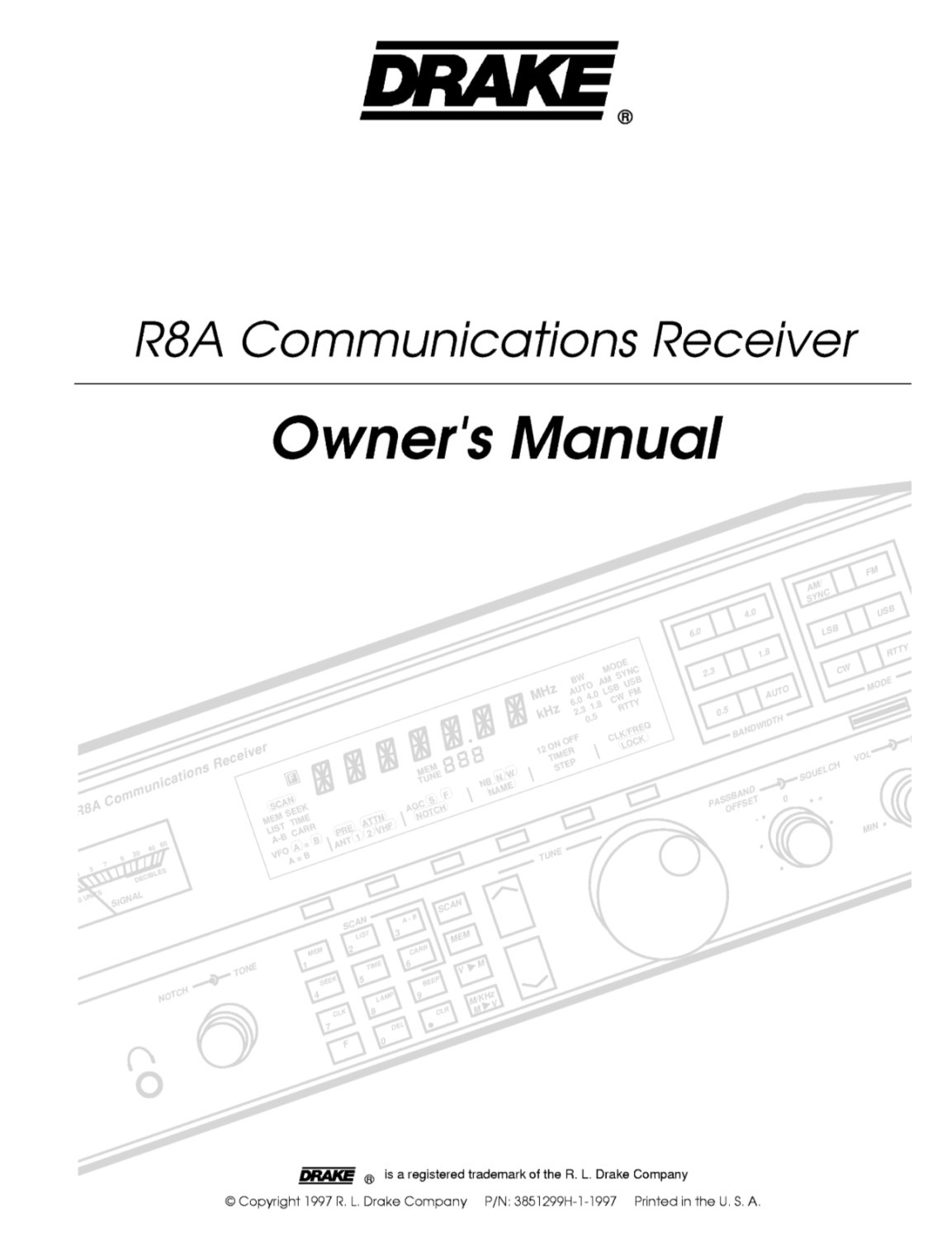
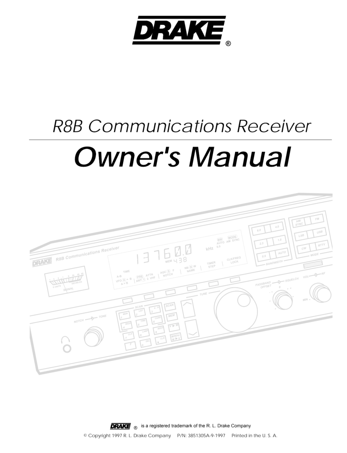


Drake R-8B – Receiver – Owners Manual 2 – 1997
44 Pages. Much Higher Resolution. …


Last Updated : 2nd September 2024

