Drake R-4B - Receiver - WB6OGD version of Sherwood Product Detector Build Instructions
First build the board as per the Sherwood schematic. C2 is soldered as shown, later it can be bent to a vertical position. As you can see, my soldering could be improved! Just make sure that everything connects and it should work fine.


I used a lug to mount the board in my R-4B by bending it flat and soldering it to the backside of the pcb which is also the necessary ground connection.
I do not have an R-4C, you are on your own for installation in the C, this article is for the R-4B though you should read and understand it before you attempt installation in the R-4C.
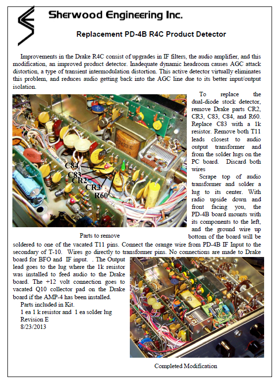
Sherwood’s article describes how his board mounts and installs in the R-4C, this board MAY install similarly,


After you have R5 and the power supply permanently hooked up, remove the temporary leads.
During actual mounting in the radio, you will poke wires through the 4 vias.
To prevent these from inadvertently touching the radio chassis, put a piece of tape on the bottom:

The last thing to figure out is how to power the board.
Sherwood took a questionable shortcut here (my opinion).
He uses R5 as a voltage drop resistor to drop the voltage from the low DC available.
He specifies two different resistor values depending if the R-4C is stock or has his Power Supply board mod.
The problem is that U1 (SA612AD) is specified to 9v Absolute Max, datasheet suggests 4.5V-8V.
My SA612AD operating with signals was measured and dropping resistor (R5) were calculated for MY available 13.7V supply as follows:
5V                   2.20mA
6V                   2.41mA           R5= 2.4K
7V                   2.64mA           R5= 2.8K    R values calculated using Ohm's Law
8V                   2.82mA           R5= 2.4K    R power is very
I used a junkbox 2.7KΩ. YOU need to measure your SA-612 current draw and your available supply voltage and do the calculation yourself to insure you do not blow your SA612! Read the Sherwood article, he has his values for R-4C installation, you MIGHT be able to just do it his way without measurement and
calculation. But if you damage the SA612 or your Drake, do not blame me!
If I ever revise this board I will include a voltage regulator, it would be safer… and easier.
On with R-4B installation…
There is a perfect place to install, right between T10 and T11 using the existing Drake screw and the previously installed lug:


If you now follow the Sherwood instructions, you will remove the Drake product detector diodes and associated components from the Drake pcb adjacent to T10 and T11.
In my method, you leave them and make one small trace cut on the Drake board and some bare wire cuts that connect T11 to the Drake board.
Then you will hook T10 to my pcb T10 connection with a small wire.
Do Not cut the bare wire from T10 to the Drake board, this is for the AM detector.
Then add a 2K leaded resistor between my board AF hole and the 0.1uf capacitor pin on the Drake board at the trace cut you previously did.
Bend Drake’s bare wire that you cut from T11, bend it and push it in and solder to my board BFO hole.
The other bare wire that you cut from T11 to the Drake board is left cut, bend it a little so it can never vibrate back!
Using my method instead of Sherwood’s, it is much easier, and much easier to put the R-4B back to stock if needed someday.
Also, the AM detector still works as original.
This commented photo is also in the Drake Files folder, you can blow that up for a better view.

The final step is to install your calculated R5 (if not done already) and wire my board 12V hole to your supply voltage.
NOTE: I already have a 13.7V supply in my R-4B for my FS-5 mod, I was able to use that.
In an otherwise stock R-4B, you are on your own! I might try stealing +10V from the PTO where
it connects to the band oscillator. An extra 2mA should not overtax it… do you think?
Downloads


Drake R-4C (Sherwood Factory Fitted) – Replacement PD-4B Product Detector – Version E
2 Pages. …
Originally Post by Gary A. Winblad (WB6OGD) 20th February 2022
Last Updated : 28th August 2024


