Drake L-4B - All-in-One Redesign
In The Beginning
The Drake L-4B Amplifier was designed and built in the middle 1960’s as a two-piece unit. This included the (L4B) amplifier section and the (L-4PS) high voltage power supply. The amplifier was a very rugged amplifier and designed as a two final tube amplifier using the 3-500 or similar tube. Over the last 40 plus years the amplifier section has survived well but the power supply is a different story. The power supply by design produced over 2500 volts at almost 1 AMP. Over time component failures in many cases has deemed the power supply as being non-repairable. Typical problems include dried out filter capacitors, load resistors opening and high voltage arcing. In most cases it is the lack of replacement parts or a bad transformer as reasons for being non-repairable. Today you can find a surplus of the L-4B amplifiers without the mating high voltage power supply. The theme of this article presents one possibility in giving the old girl a new life.
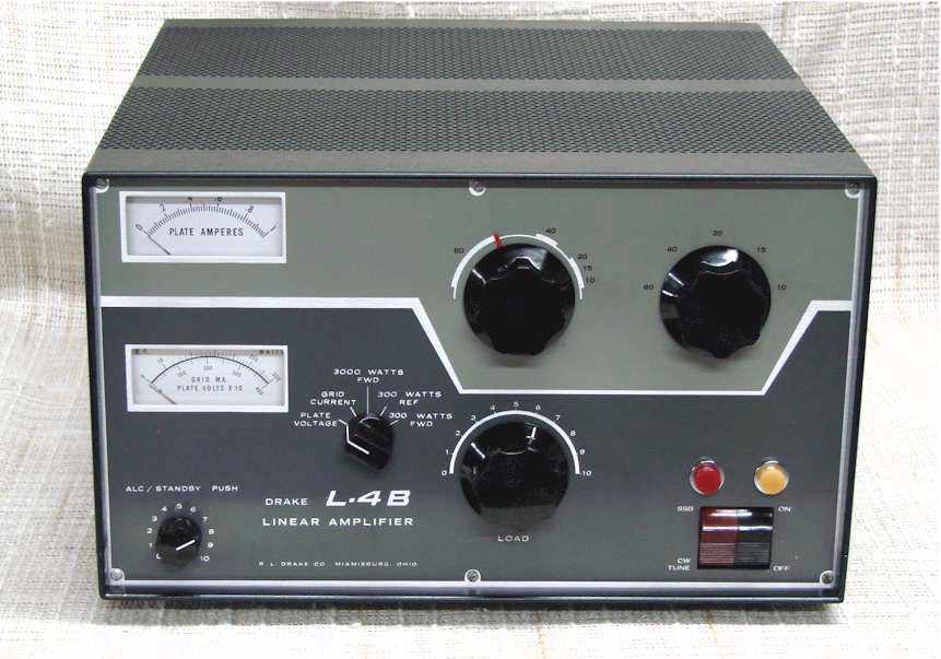
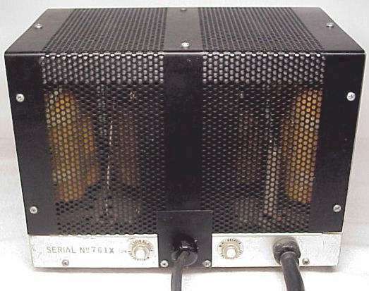
Shown in the pictures below is the original Drake L-4B amplifier and the mating L-4PS high voltage power supply which Drake Manufacturing sold between 1965 to around 1979. The earlier version of the L4B the front panel had the silver edging around the outside edge of the front panel all around, this matched with the Drake B-Line series. The later version of the L-4B the front panel was painted edge to edge to match with the newer Drake C-Line.
The L-4B Amplifier Chassis Redesign
Today you can find the L-4B amplifier without the L-4PS power supply from several sources, such as hamfests and through the e-Bay auctions. There is not much you can do with an L4B Amplifier without the power supply, so what are your options. Those include finding another working power supply, or one that can be repaired, or, building up a home-brew version. One another option, described in this article is to build the power supply inside the L-4B Amplifier. Granted after the conversion is completed it no longer has the same power output capability as the original L-4B, but it does make a nice completely self-contained tabletop amplifier that with 80 watts of drive, will produce around 750 watts output.
This L-4B project started with an amplifier parts chassis I acquired with most of the major components and the front panel removed. So not only was this a power supply conversion, it also was a restoration project, giving the L-4B a second chance to live again.
Building a high voltage power supply on the L4B chassis is a real challenge because of the lack of space. First you need to determine where and how to place the large high voltage transformer. To begin with the L4B chassis is well packed, so something needs to be eliminated to create enough space. After staring at the chassis for a while I decided the blower and one of the 3-500 final tubes had to go.
In order to do this it meant stripping the entire chassis of all above chassis components to have room to work.
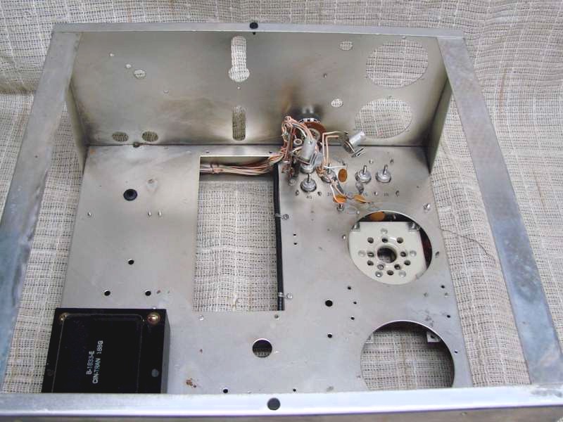
The blower is easy to remove knowing it will never go back in. It is held in place with several screws into the back of the chassis. Second, I removing the rear final tube and socket socket, this give me sufficient room for the power transformer along the back side of the chassis. The only problem is this leaves large holes in the chassis making it difficult to mount the transformer, and the rear panel where the blower was placed.
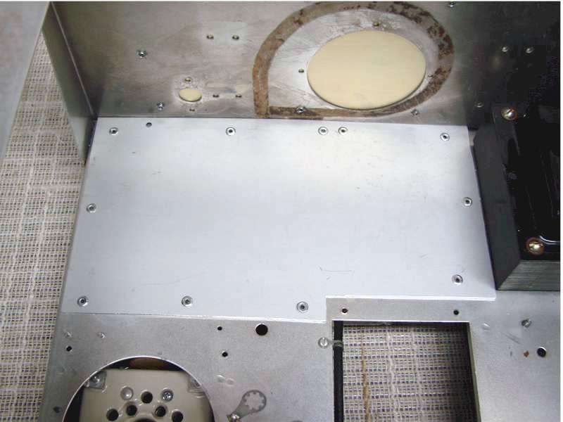
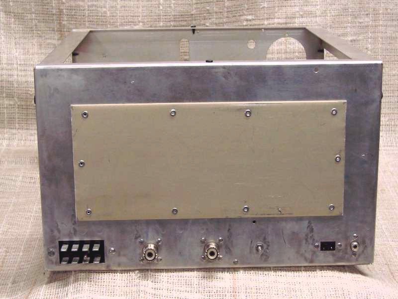
To solve this problem, I cut out an aluminium plates to cover the back half of the chassis and the rear panel, and pop riveted those in place.
This now allows ample room to mount the high voltage transformer to the chassis along the back wall of the chassis next to the filament transformer, and provides the mechanical support to mount the heavy power transformer. The new panel on the rear of the chassis is mostly for cosmetics, to hide the blower holes and the transformer inside.
High Voltage Transformer Installation
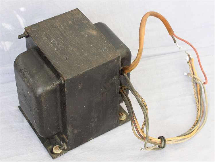
The first challenge when looking for replacement parts was finding the right high voltage transformer that not only is the right size to fit the chassis but having the right voltage and current capabilities. I searched several sources for a compatible high voltage transformer and settled on the transformer from a Heathkit SB-220 Amplifier.
The transformer seemed to be a good fit, it does produce a little more high voltage, and it is a bit smaller than the transformer in the original L-4PS power supply. It has the dual 110VAC primary windings to operate at 110 or 220VAC and has tapped secondary high voltage windings for the “Tune” and “Operate” Modes.

Under the chassis, shown below, I brought both primary windings to a terminal strip so it could easily be wired to operate at 110 or 220 volts. Each primary winding is a tapped winding which is used to switch between the “Tune” and “Operate” modes.
Since that switching is the same for either the 110- or 220-volt operating voltage I used a small relay to do that switching. This way I eliminated the vulnerability of the power switch contacts from arcing internally and welding together due to the high current being switched.
This is a very common problem in that power switch which prevents it from switching between the “Tune” and “Operate” mode.
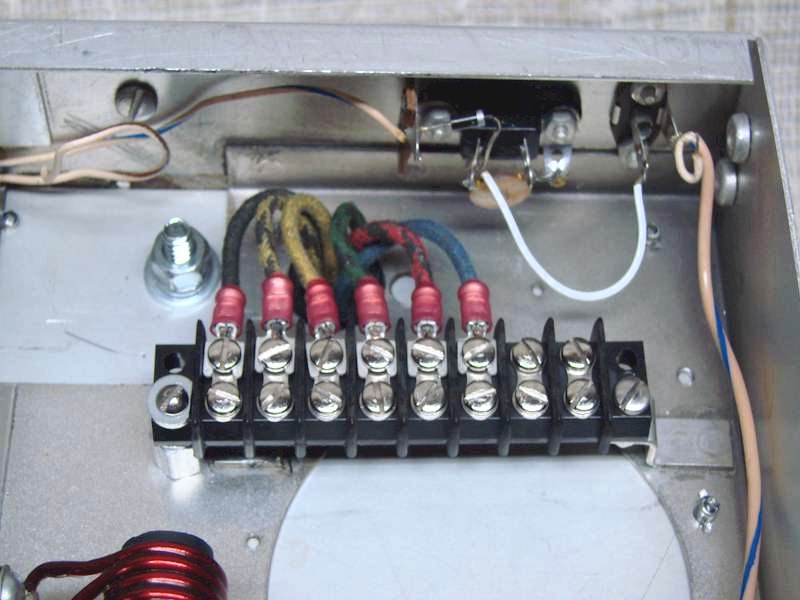
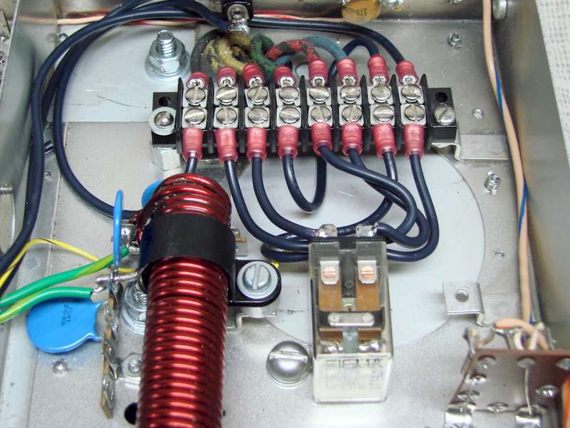
The photo above-left shows the transformer primary wiring to the terminal strip.
From left to right the two primary winding are in groups of three wires. In each group the black dual colour stripped wire is the tapped connection to the winding.
In the picture on the right shows the wiring for 220 VAC operation. The relay switches the winding tap connections for the “Tune” or “Operate” mode.
The difference being lower high voltage for amplifier tune-up purposes and the Power output between “Tune” to “Operate” is approximately 150 watts of additional power.
The relay now operates from the front panel “Tune / SSB” switch to the low voltage power supply. This eliminates the common problem of the front panel power switch arcing and welding the switch contacts together.
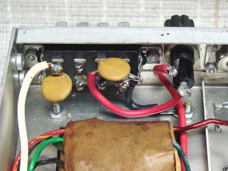
The large 8 pin connector on back of the L4B chassis, originally connected to the L-4PS power supply is now the primary power connector for the new design.
The connector, depending on how the amplifier is jumpered internally, will except either 110VAC / 220VAC input.
The circuit breaker protection for the amplifier was originally in the L-4PS power supply. In my design there is very little rear chassis space to accommodate circuit breakers, so I decided to use fuse holders. Since there are now two transformers each receiving primary power, I decided to install a separate fuse holder for each one. Shown in the picture to the left next to the 8-pin power connector is the chassis mounted fuse holder for the filament transformer. The high voltage transformer fuse holder is the same type of fuse holder but mounted on the other end of the chassis near the high voltage transformer. Both fuse holders use a 15 AMP fuse for 110VAC or 10 AMP fuse for 220VAC.
Input Circuit Redesign
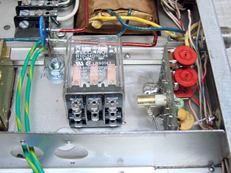
When considering the underside chassis component layout, I wanted to keep as much of the wiring as original as possible. I also wanted to replace the antenna relay with a new sealed relay. The new relay is about 50 percent bigger than the original relay, so mounting the relay where I could get to and solder the terminals became my first issue. I quickly came to the realization I would need to move some of the components around or eliminate them to allow for the much-needed relay space.
Along the back where the original relay was located seemed to be the best spot since it was directly in line with both the RF input and output connectors. The only problem with that space was the watt meter board and the two large feed-through capacitors in the filament circuit which were both in the way.
I never knew why Drake used this style of feed-through capacitor, but I knew that they needed to go.
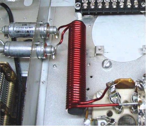
Those capacitors along with the large bifilar choke isolates the RF input power from the ground potential through the filament power transformer. The bifilar choke is attached to the first tube socket. The tube filaments are in parallel, so I just cut the leads going over to the second tube when I removed the rear tube socket.
Shown in the second picture to the left is a close-up of the remaining tube socket. The original bifilar choke is attached to the first tube socket which was left in place. You can see along the bottom of the socket where the copper strapping was cut at the tube pins going to the second tube socket that was removed. I also added that disc capacitor to make sure the RF drive was equally distributed across both sides of the tube filaments.
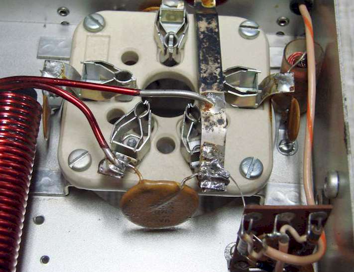
I decided to remove the large feed through capacitors and add smaller disk capacitors of the same value to both sides of the circuit to ground. I also added the same value capacitor across both lines to ensure any stray RF signal was eliminated at this point.
The basic function of this circuit is to pass the filament voltage to the tubes and completely isolate the RF input signal from the ground potential through the power transformer.
The input power from the exciter is routed through the antenna relay directly to the tube filaments.
The L-4B design is “grounded grid”, so in this case the input power is applied to the tube filaments since there is no separate cathode. Shown in the picture below is the feed-through capacitor resign.
You can see the blue disk capacitors on the left going to ground from each side of the transformer and on the right the single blue disk capacitor going across the two leads from the bifilar choke. This configuration provides the additional space for the relay, however, with the watt meter board in the same area still makes it a tight fit. The watt meter board runs perpendicular to the rear panel. By turning that board 90° in the same area provide plenty of room to mount the new antenna relay and access the contacts for wiring.
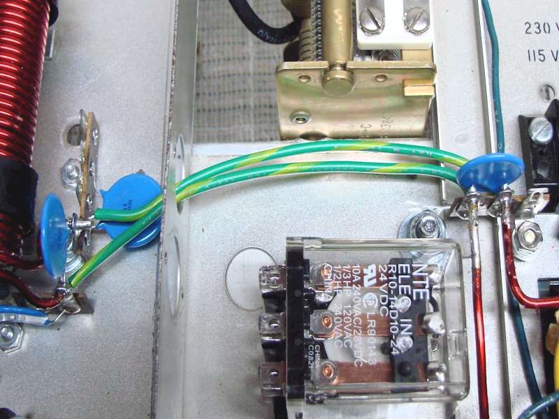
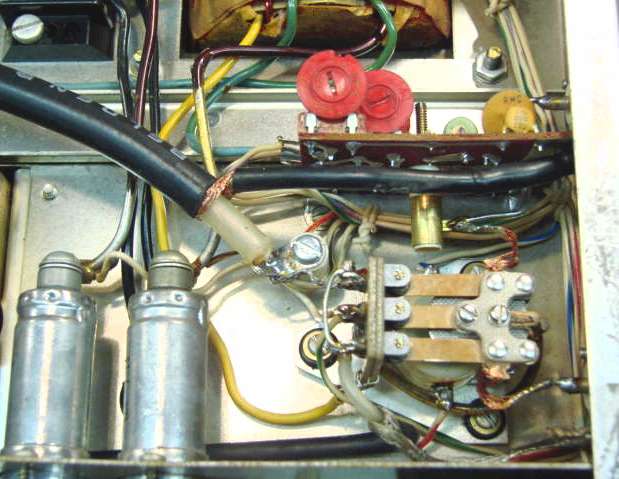
Shown the pictures below, on the left, is the new antenna relay mounted and the watt meter board turned 90 degrees and remounted parallel with the chassis rear. Remounting this board this way gives easy access the red watt meter calibration controls and puts it directly in front of the RF input and output connectors.
The other picture below, on the right, shows the “before modification”, how the original relay and watt meter board are mounted in the L-4B Amplifier. Also, note the large feed through capacitors in the filament circuit were removed in the modified L-4B design to make room for the new larger antenna switching relay.
Chassis Reassembly
Installing the Output Tuning Components
After the high voltage transformer was mounted the next step was to remount the output tank components and other hardware that was going to be reused.
First, I remounted the loading capacitor and the tank coil and band switch. As you can see in the picture on the left the transformer placement was critical leaving only a small amount of clearance between the output tuning network. Both large coils in the tank circuit are silver plated. Over the years those became tarnished. Before reinstalling them, I did some cleaning making them shiny and looking like new again.
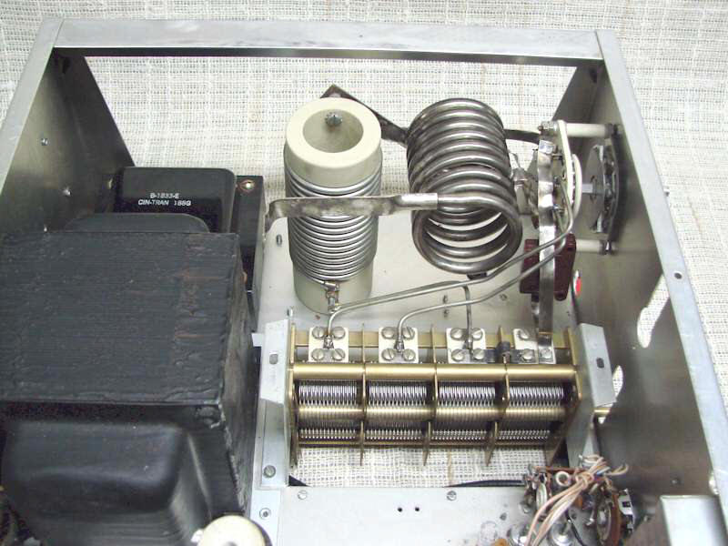
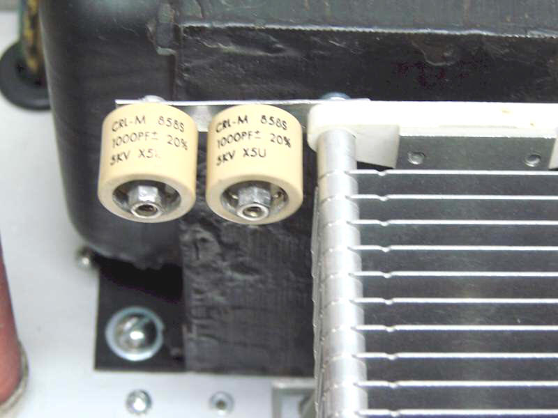
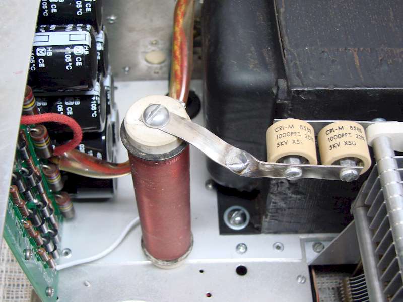
In this picture the plate tuning capacitor is mounted and connected into the circuit. Also mounted to the tuning capacitor are two doorknob coupling capacitors going to the final tube plate. I had to make a small bracket to mount those capacitors to keep them far enough away from the transformer to prevent arcing. There is roughly 3/4 of an inch clearance which is enough room to not interfere with the tuning or the 2800VDC from arcing to the transformer.
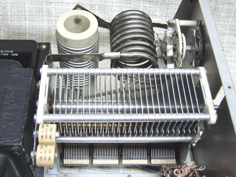
Shown in the picture here on the right is a close-up view of how the doorknob capacitors were mounted to the plate tuning capacitor.
Next, I reassembled the front panel components. First, I put back the two meters and wired them into the circuit, Next I installed a modified Standby/AGC switch, the switch drive chain, and the Power switches. There is a short story about the power switches. When I got the L-4B chassis the switches were both white and definitely not the right type.
The Red and Black Power switch assembly is rare and hard to find. eBay is usually a good resource for parts. Knowing I would be needing a new switch assembly I watched eBay for several weeks with no luck. The day came when I needed to mount the power switch and was going to use the old white switches I had. Just then an original switch appears on eBay. Well, this switch was critical for keeping the amplifier looking original, thankfully I won that auction but that switch assembly cost me $125.00, plus shipping. Yes, I cried a little, but knew it was essential to keeping the amplifier original looking.
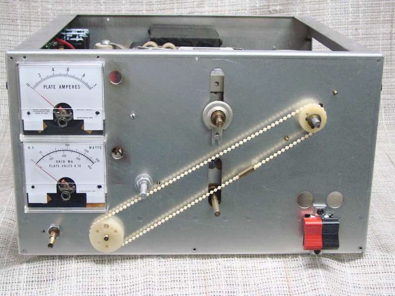
Remember I said earlier I mounted a slightly modified Standby/AGC switch. In the L-4PS power supply there is a 5KΩ, 10-watt resistor that is a common failure in the power supply. When it goes bad, the resistor opens up, which takes away the ground potential for the high voltage filter capacitors. That in turn puts high voltage on the AGC control which immediately burns the control open. It only takes a few seconds for the control to be destroyed. This is another component in the L-4B that is very hard to find, and the chassis I acquired the control was bad.
Looking through my junk box of controls I found a control out of an old Heathkit HW104 which was the right resistance value, a pull switch, and it also had a long shaft. The problem was the control was a dual control pot and the control section I needed was attached to the off/on switch and the inner shaft which is too small to attach a Drake bar knob.
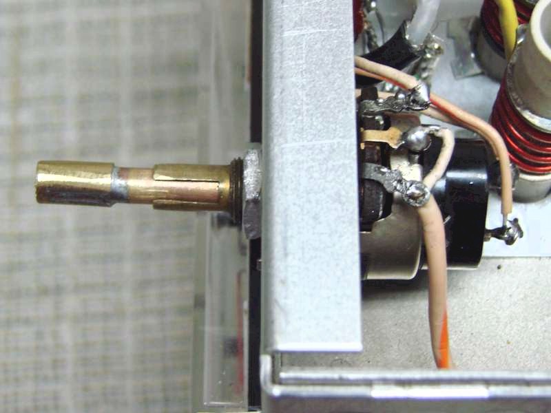
To make long story short, I cut off the outer shaft, so it stays behind the front panel. The inner smaller diameter shaft is now long enough to stick through the front panel but not the right diameter to mount the knob. To make the inner shaft the right diameter for the knob I soldered the outer shaft piece I cut off to the end of the smaller inner shaft. So now with the outer shaft cut off and hidden behind the front panel, the inner shaft is the right length and size to extend out from the front panel and mount the proper Drake knob. From the front of the amplifier, you cannot tell it from the original control. Shown in the picture on the left is that AGC/Standby control showing the modification I made.
The New High Voltage Circuit Board
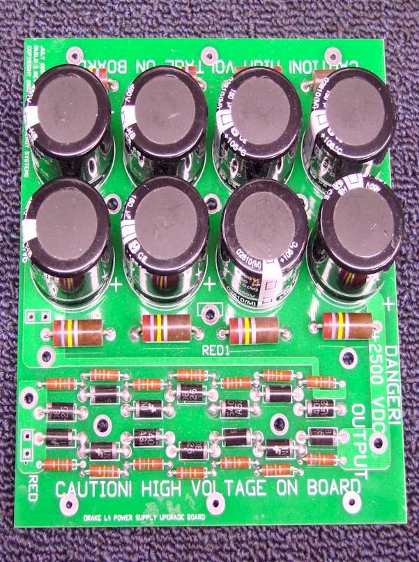
From the beginning my plan for the high voltage board was to install one of these newly designed upgrade board on the market. I had thought about doing regular hand wiring but mounting all the filter capacitors and other components became a legalistic problem with the limited space above and below the chassis. There are a couple of sources for the upgrade kit for the L-4PS power supply. This is a single board which contains all the high voltage components neatly arranged in a compact package. I choose to use the Heathkit Shop upgrade kit because their board is made with a high-quality epoxy board, and it includes equalization resistors across the filter capacitors and rectifiers.
In the picture on the right shows the Heathkit Shop board completely assembled and ready to install. You will notice that each filter capacitor and rectifier has equalizing resistors. The board layout is very nice and neat, and the board is labelled very well to minimize mistakes being made.
At first, I wasn’t quite sure how I would mount the board, but quickly concluded it needed to be mounted on top side of the chassis. I found that I had three options for mounting. I could side mount the board vertically on the right or left side towards the rear. The third option, which I ruled out quickly was to suspend the board on stilts placing the board along the top of the amplifier just under the case top. I quickly realized this would be a nightmare from a mounting and cooling prospective.
Mounting the board on the left side provided very little clearance between the filament transformer.
I found the right side towards the rear worked the best. There was plenty of room to mount the board and plenty of clearance to prevent arcing to the chassis or other components in the same area. The board was now close enough to the power transformer, so the leads reached the board without extending them, and only a couple of inches to reach the high voltage isolation choke supplying the voltage to the tube plate circuit.
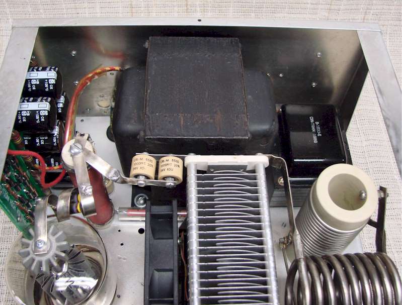
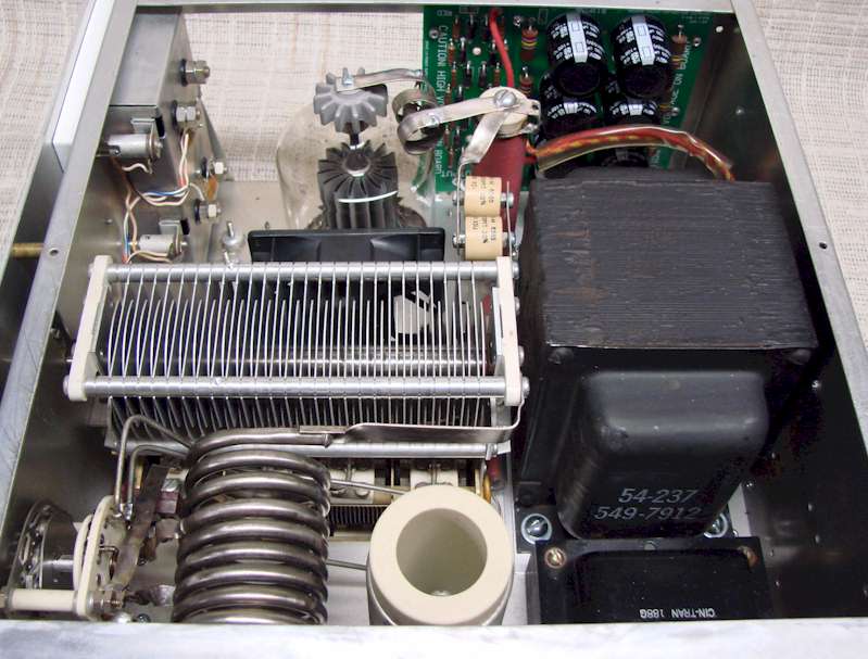
In the pictures below are a couple of different angles showing how the high voltage board was mounted. As you can see there is plenty of clearance from the other components to prevent arcing, and the transformer and high voltage plate choke and still close enough to make the connections to them very short. You will also notice in the picture on the left where I fabricated a bracket to mount the high voltage blocking capacitors to the plate tuning capacitor and attaching to the top of the plate choke.
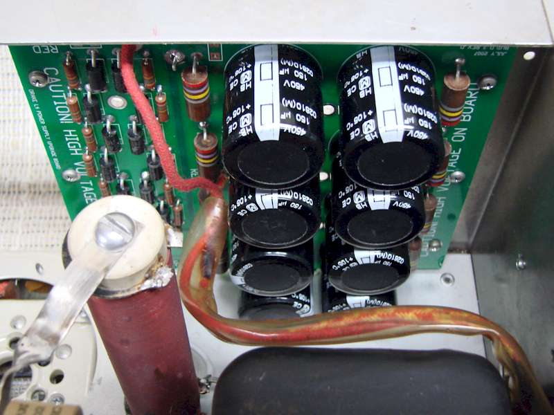
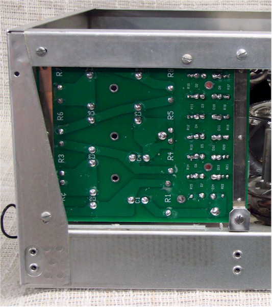
The picture on the left here shows how the board was mounted to the chassis. In each corner of the board there are mounting holes which I used to attach the board to the side of the chassis.
The board was mounted inside the top side rail about a 1/4″ down from the top and along the backside of the chassis. I used 3/8″ metal stand-offs to keep the board away from the chassis to prevent arcing, and to provide a solid ground connection to the board in all four corners. Along the bottom of the board, I mount the board to the rear vertical chassis support just like I did at the top.
The lower front of the board there was nothing to mount that corner to. Initially I was going to leave that corner hanging and it would have been stable, but I decided to fabricate a small “L” shape bracket, mounting it to the chassis to hold that corner of the board in place.
Mounting the high voltage board in this position turned out to be the best possible location. It is back far enough so that it does not interfere with the cooling fan air flow and has plenty of room for the heat generated from the board itself to escape and has enough clearance to prevent arcing and keeping all the connecting leads fairly short.
Amplifier Metering and Cooling Functions
The L-4B Amplifier metering functions were basically kept the same as the original design, but a few components needed to be moved around.
The plate current meter function was left unchanged, but now that only one tube is being used the plate current meter calibration changed, so that needed to be recalibrated. The calibration control, white control just below the meters, has plenty of range so no component changes were needed.
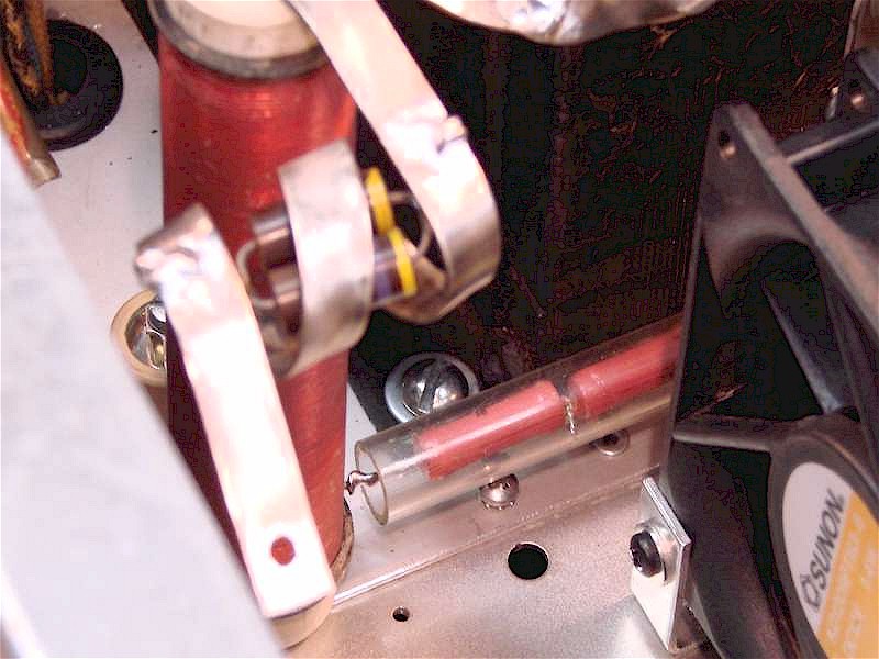
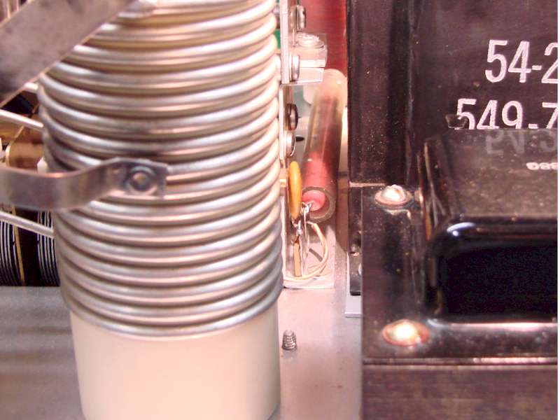
The power supply voltage metering required some component relocation since the high voltage divider resistor network was located down the left side of the plate tuning capacitor, which is now where the cooling fan is placed. The high voltage resistor divider network consists of four 10 meg-ohm resistors inside a plastic tube which runs parallel along the left side of the plate tuning capacitor.
The final tube plate isolation choke was moved slightly back from the original position. That choke is now directly in line with a small 3/4″ wide gap between the front edge of the high voltage transformer and the rear of the plate tuning capacitor and the rear side of the fan. The resistor divider network fits nicely down this narrow space which can be seen in the second picture below. One end of the resistor divider network is soldered to the base of the plate choke to sample the plate voltage. The divider network slides down in that narrow open slot and is attached on the other end to a terminal strip just in front of the filament transformer. The wire from the low side of the resistor divider network goes under the chassis back to the meter function switch.
The picture above shows the resistor divider network soldered to the base of the plate choke.
The picture on the right shows the resistor divider network placed between the high voltage and filament transformers and plate tuning capacitor and output loading coil.
The other end of the resistor divider network is soldered to a terminal strip and held in place by both ends of the soldered connections.
The clear plastic tube holding the resistor network is fairly thick and insulates the resistors so they can be placed close to the chassis and other components without fear of arcing.
The original cooling fan design in the L-4B was a 90° squirrel cage fan blowing air under the chassis through a channel and up through the tube sockets. The air pressure would blow up through the tube socket and around the tube and exit through the top of the chimney. This concept worked well for cooling, but the blower was noisy and took up a large area of the chassis. For the redesigned L4B this blower was the first item to be removed to make room for the high voltage transformer.
The redesign made the L-4B a very compact with no room for that big blower. Also since there was only one tube in the amplifier so less cooling would be needed. The direct air flow method of cooling seemed to be the most practical method. Since several other amplifiers such as the Collins 30L-1 and the Heathkit SB-200 and SB-220 used the same type of cooling, this proved to be an acceptable cooling method.
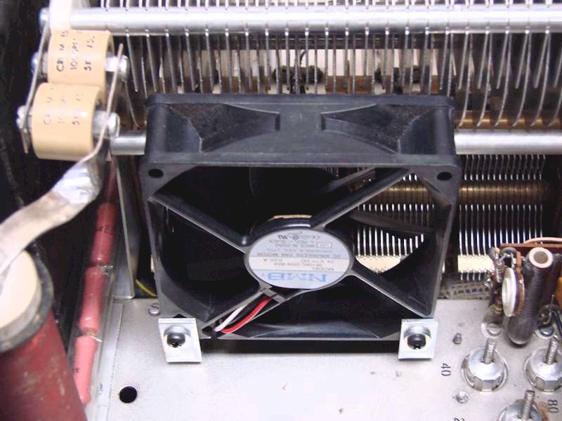
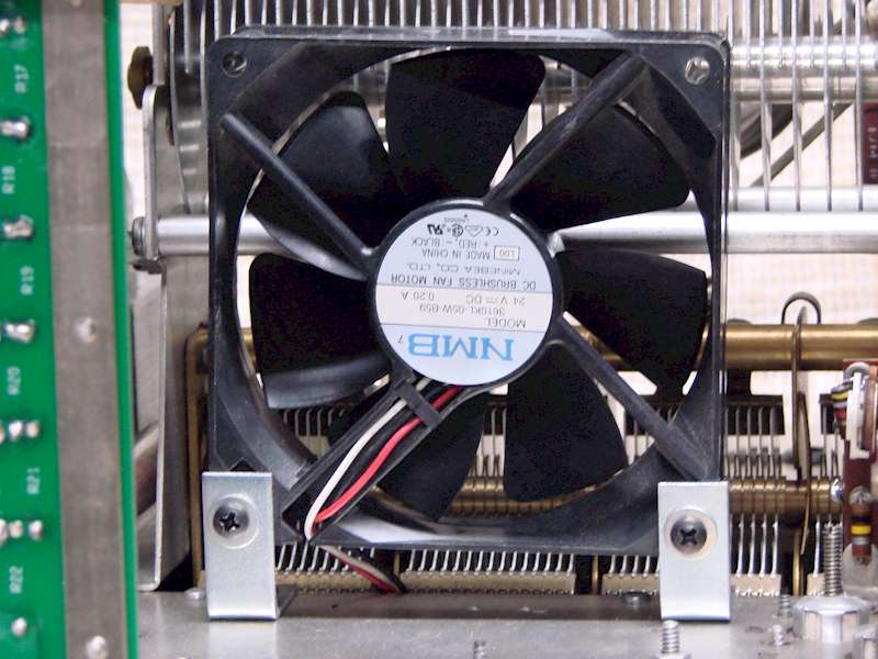
In the L-4B redesign I found the open area between the final tube and the plate tuning capacitor was the best location for the fan. There was just enough room to locate a small 5-inch muffin fan with enough room on all sides so it would not interfere with the other components. Mounting the fan was accomplished with a one inch 90° bracket bolted to both sides of the fan and to the chassis. I choose a 12VDC fan which I wired to a 12-volt low voltage power supply under the chassis and wired in for continuous operation.
The picture above right shows the fan assembly mounted to the chassis and to the right side of the final tube. The fan blows across and around the tube and exhausts out the left side of the amplifier. The picture to the right is another view of the fan and how it was mounted to the chassis.
The New Low Voltage Power Supply
The original L-4B low voltage power supply design was a half wave rectifier powered from a low voltage winding on the filament transformer. Its only function was to deliver unregulated +24 volts to power the antenna switching relay. The new power supply design not only powered the antenna relay, but also powered the TUNE/SSB Mode relay, provided the ACG bias, the final tube fan, and power to the front panel pilot lamps. The new design included the same half wave rectification as before, but also includes a plus 12VDC regulated output.
Both the antenna switching relay and the TUNE/SSB mode switching relays are 24V relay coils. The +24VDC output did not need to be regulated since voltage fluctuations was not an issue for the relays or the AGC bias. The pilot lamp and fan voltage were a different situation.
Both the original pilot lamps were neon bulbs which operate around 100VDC. This voltage came from a divider network in the L4PS high voltage power supply. Since that was no longer used, I had to come up with a different lamp powering method.
I wanted to keep the front panel with the original look, so using a different type of lamp assembly was not an option. So, I pulled out the pilot lamp from inside the holder and replaced the neon bulbs with a 12-volt lamps with wire leads.
Using a small amount of hot glue in the back of the holder held the bulb firmly in place. I first hooked the pilot lamps directly to the power supply using load resistor to drop the voltage to 12 volts. I quickly found the unregulated voltage changed enough between transmit and receive modes and between the TUNE/SSB modes that the lamps constantly changed their brilliance level with each amplifier function change. To resolve the lamp flickering I added a +12VDC regulated output. This kept the lamps at a constant voltage and constant lamp brilliance no matter the mode or function selection. I also had the same issue with the final tube fan, with the change in voltage the fan speed would change slightly. It did not seem to affect the cooling capacity, but you could hear the changing fan speed. Hooking the fan on the regulated 12VDC side now kept the fan at a constant speed.
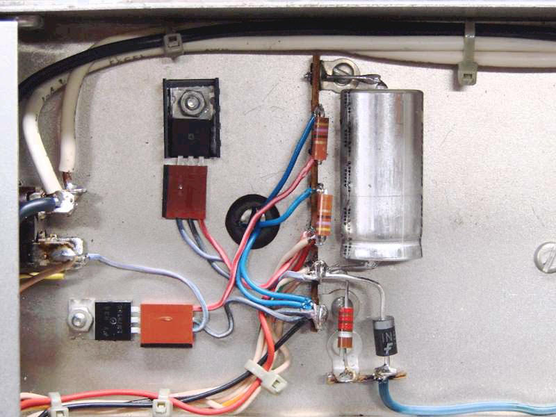
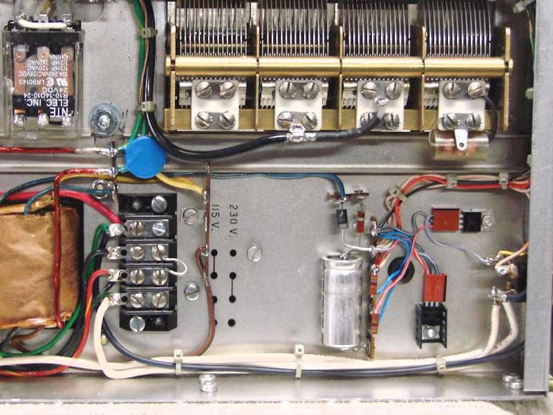
Here is a close-up view of the power supply area under the chassis. On the right side is the rectifier and filter capacitor making up the power supply with the large blue wire coming from the filament transformer at the bottom.
The +12VDC regulator is located at the top left with the heat sink.
This supplies power to both front panel lamps through the 47Ω load resistors and power to the fan.
To the far bottom left is the backside of the red & black power switch.
The black half of the dual switch assembly still switches primary power, and the red side now switches a low voltage to the SSB/CW Mode relay which protects in from high current failure.
This is the most common problem with these switches which this design solves.
New Redesigned Panel Lamps
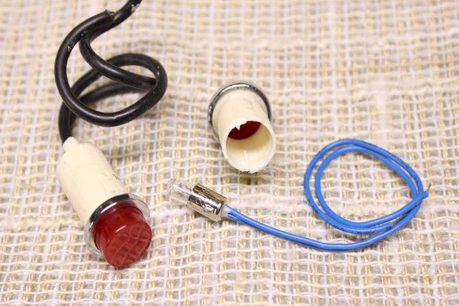
I mentioned in the previous section that I modified the panel lamps from the original 110VAC neon lamps to a 12VDC powered lamp.
The conversion process was simple, I cut off the back end of the lamp housing off and pulled out the neon bulb assembly.
The picture to the left shows the original L-4B lamp on the left side and on the right is the lamp with the rear cut-off and neon lamp assembly removed.
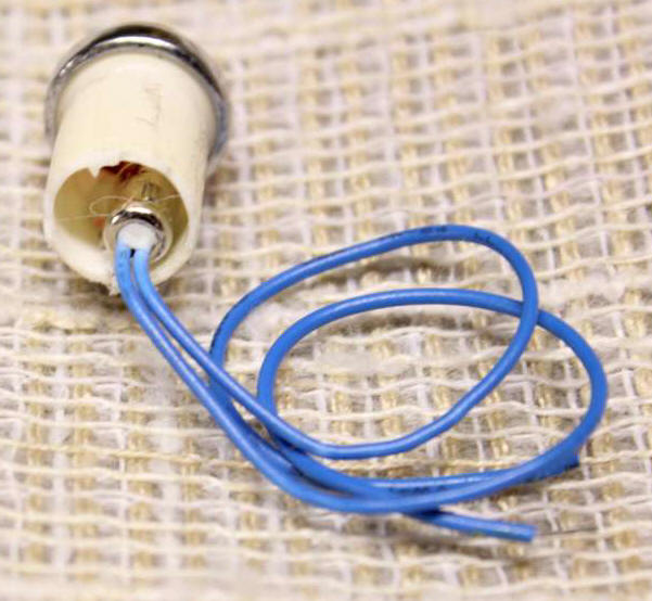
The 12 VDC lamp with the blue leads is then inserted in the back of the lamp holder and held in place with a small amount hot glue, as shown in the small picture below. This will hold the lamp in place but will snap loose easily to replace the lamp in case it goes bad.
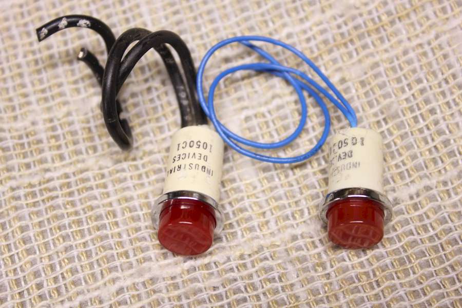
In the picture below, you can compare the L-4B original neon panel lamp next to the completed modified lamp I used in the amplifier redesign.
The L-4B has two front panel lamps, the orange colour lamp indicates main power is on, and the red lamp indicates the amplifier is in the SSB mode and the higher voltage level is selected for the final tubes.
Both lamps were modified identically, and the bulb’s brightness level is as good or better than the original neon bulbs.
The Completed Single Tube Version of The Drake L4B Amplifier
Here are pictures of the finished L-4B amplifier redesign.
My original goal was to incorporate the high voltage power supply inside the amplifier housing.
The biggest change was the elimination of one of the 3-500 final tubes and the large blower to make room for the power transformer.
The changes also included adding the Heathkit Shop upgrade power supply board, a larger sealed antenna switching relay, and a regulated low voltage power supply.
From the outside the Drake L-4B Amplifier looks all original and all the metering and tuning functions operate just like the original version.
The only significant difference on the rear panel is the elimination of the high voltage connector, and the large 8 pin connector where the L-4PS power supply attached is now the primary input power connector.
The amplifier will work on either 110VAC or 220VAC with changing jumpers under the chassis for each or the two power transformers.
Putting the amplifier on the air the results were just as I was hoping for.
Operating with one tube worked fine, I had no problems with loading or tuning up on any of the ham bands.
The high voltage transformer from the SB-220 fit perfectly and has about 200 volts more output over the Drake L-4PS power supply.
On 80 through 20 meters. I am getting 750 watts output and on 15 and 10 meters around 600 to 650 watts output.
The amplifier has been on the air several times and has worked perfectly with good signal reports.
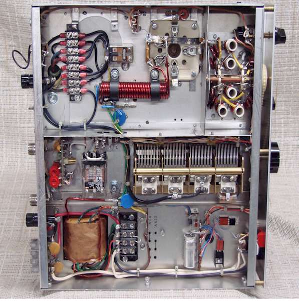
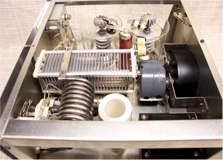
Shown in the pictures below are the completed chassis modifications. The first picture shows the amplifier front, the next three pictures show the inside top view and under chassis view.
The last picture at the bottom shows the original L-4B chassis layout to compare with the redesigned chassis.

In conclusion, I hope you enjoyed this article as much as I enjoyed designing and building up this modified L-4B amplifier. This project started as an idea I had in my head for several years, and during that time I thought about how it would look in the end.
Over the last few years, I looked for the opportunity to make my dream project a reality. It wasn’t until mid 2010 that I came across an L-4B chassis that was a parts chassis.
As I now look back over the last several months of rebuilding the amplifier, I decided it was a “labour of love”. It had to be that, and only that, because after I added up all I spent for parts alone, from a financial standpoint I could have bought a new amplifier.
Thanks for reading my article.
Keep your filaments lit and the tubes glowing strong, it is our heritage and a legacy of love.
Originally Posted by Ron Baker / WB4HFN
Last Updated : 26th August 2024
