It’s ben years since I last bought and made a kit, the last one I think was the Cumbria Designs CW Morse Code Reader, so this has a lot to look up to.
The Kanga Products FMT Mk4 CW Trainer was something that I thought that I needed, the voice box has been well and truly destroyed thanks to radiotherapy and recover will be very slow, I can croak with the best of them but any amount of talking has two main effects, It hurts after a while and I end up with a very dry mouth having no saliva as well so I certainly will not be able to handle talking over the radio for hours on end, I really hope that I can at least get back a little of what Godfrey (GD4EIP) had taught me many years ago.
Another side effect of the Cancer treatnment has been the lack of concerntration. I seem to feelmyself drifting off, so it is going to be a lot harder for me to pick this back up than it was before, so I thought that a good CW trainer would be a worthy purchase, and bar a few antique version found on Flea Bay, I decided to go with this model for no other reason than it looked like the best alternative.
I am not really making this sound good am I?
You Get What you Pay For, or Do You? Big Surprise on it's way...
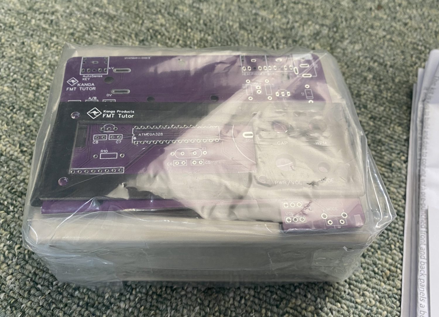
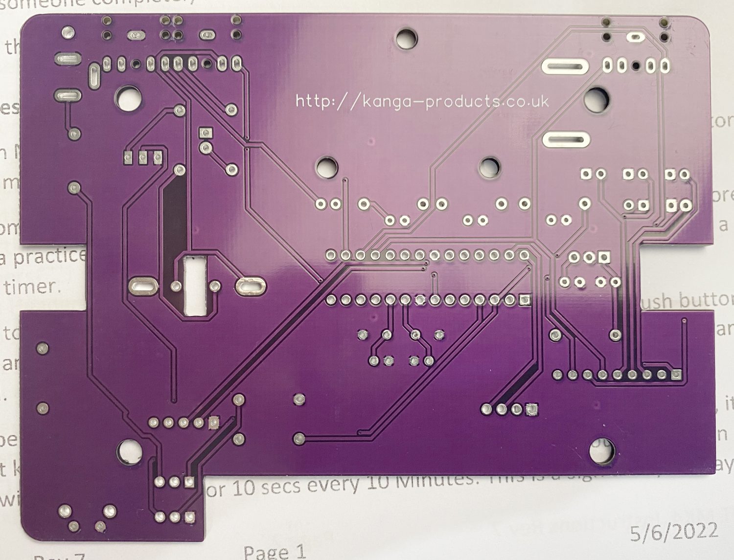
I does come well packaged and in a plain white box, in my case case I noticed a rather sexy looking ‘Purple’ PCB under the plastic and some pre- printed end panels for the cabinet.
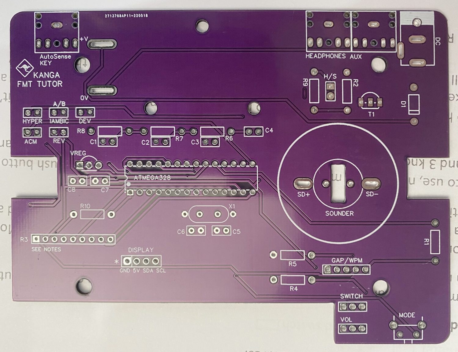
It does seem to be a very simple kit, but some thought has gone into the kit, the PCB in it’s vivid Purple is a rather nicely laid out 2 sided PCB, not your normal cheap Chinese mass produced board, so the creator has put a bit of effort into this.
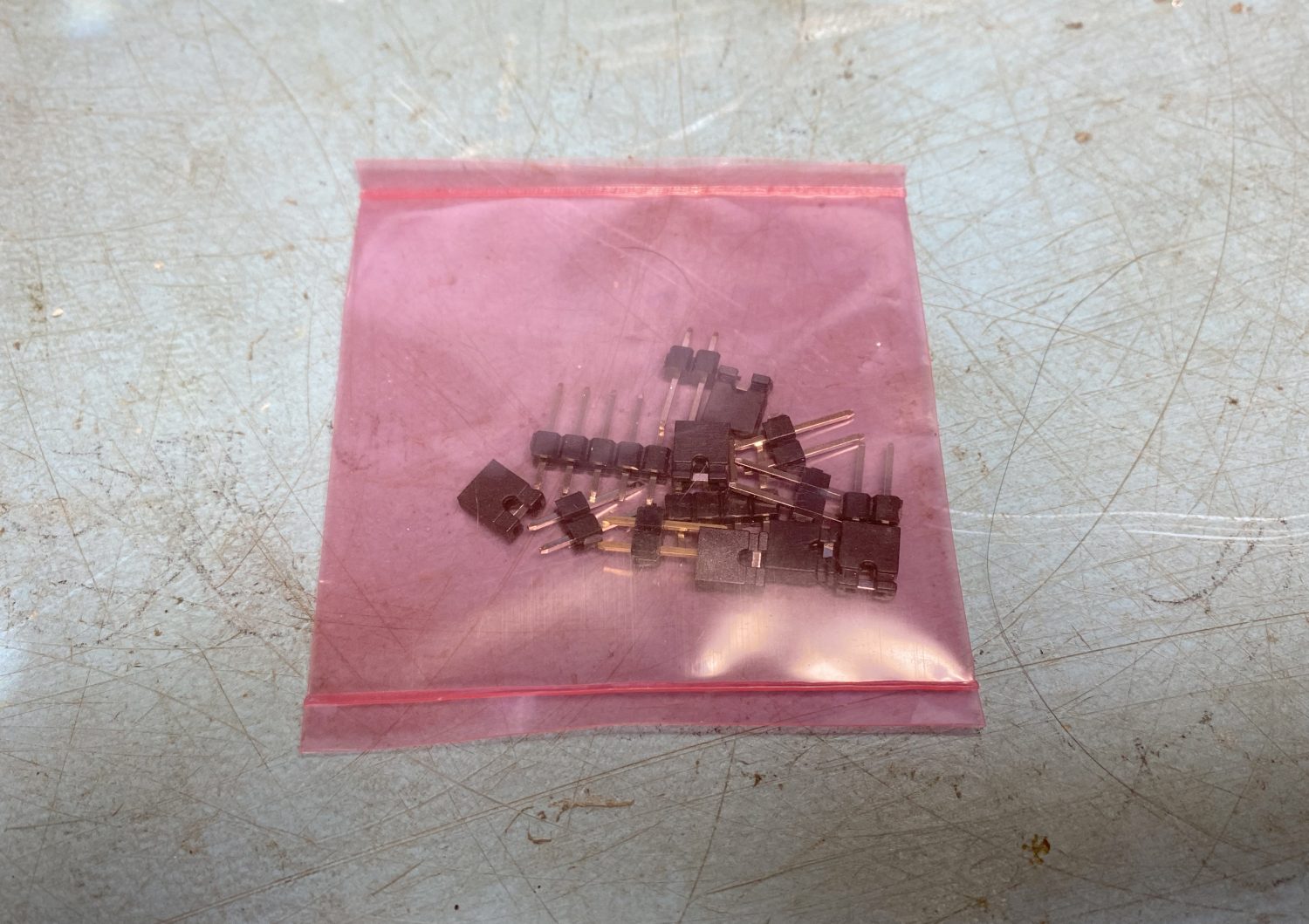
The bag of parts once ripped apart by the way too big knife, reveals 8 Anti-Static sealed bags which I presume at this time is for each stage of the build.
There are no surface mount components here which is good because I cant find the well hot air gun, and the quality of the components does look to be pretty good so far.
I said at the top of this bit that you get what you pay for, and in this case I am presently surprised., certainly not military specked components, but from the look of it not too cheap a versions either.
Hopefully more on this later…
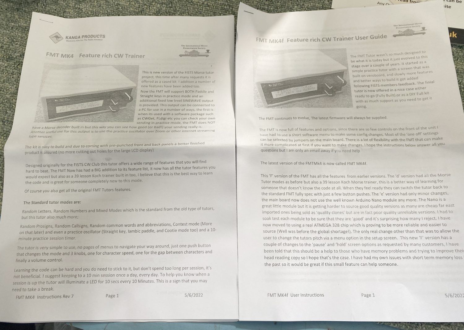
The supplied documentation from Kanga Products for the FMT Mk4 CW Trainer.
Now the only part that I have to say is a little bit of a let down, but it’s not too much of a problem – The Manuals.
The printouts look as though the toner was dying in my case.
But thankfully they also have some very nice versions on there website, please click on the images below to download direct from their website.
Hopefully the links will not go down, but have download copies just in case I need to update my links.
The full kit all nicely packaged up ready for the fun of building.
Please ‘Click’ on the two images below to download the manuals from the Kanga Products website
At the time I purchased this kit we are up to Revision 7 of the manual that is 11 Pages of nicely laid out instructions that even I could follow with my wonky head.
Kanga Products FMT Mk4 CW Trainer – User Manual
That is 10 Pages of nicely laid out User Guide, I looks to be OK but time will tell.
The Build - The Fun Bit...
Before we start I should shout out a few recommendations here:
Soldering Iron – Please do not use any rubbish ones here, if you are building kits or doing repairs then you should already own a good quality soldering iron with a fine tip such as a Weller, some of the pins on this kit are fairly close to each other and you really do not want to go at this with something with a large tip that you could use for digging the garden with.
Solder – Same goes for this, Use what you are used to but please do not think of using any thick solder, you should get the finest that you can find and please avoid that rubbish ‘Lead Free’ Crap, it really is a waste of time using it.
Side Cutters – I could not find my nice set and in the end had to resort to a cheap pair that I got from CPC ages ago, but if possible get yourself a good quality small side cutter for lopping off the legs of the components, not too essential for this kit, but always advisable to have a good set to hand.
Magnifying Lens – My eyesight is fading with age and months of Chemotherapy and Radiotherapy have not helped, so if you can get a desk mounted light with a magnifying lens in it it will be a great help, This is no way near as hard as working with Surface Mounted devices (SMD), but why make things hard for yourself…
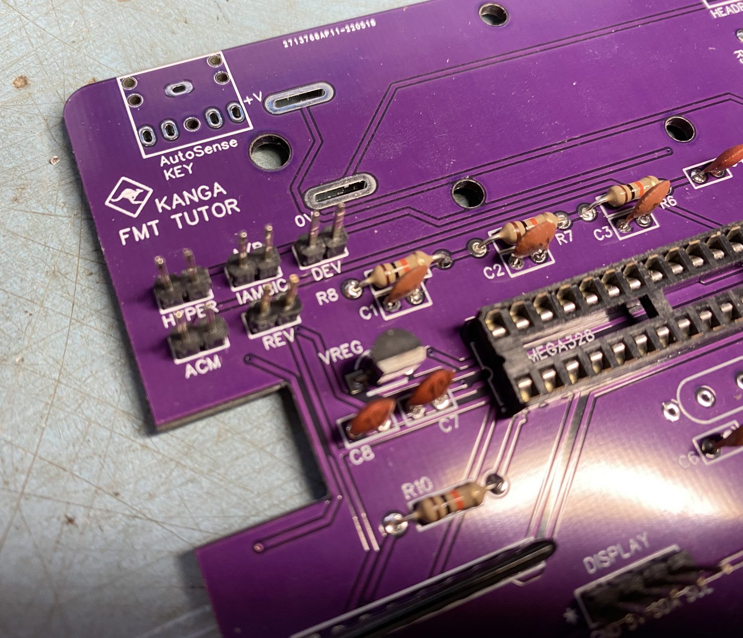
The first section of the manual is taken up with a ‘Parts List”, worth going through…
And get a better look at those lovely Purple PCB’s, that’s sex on legs for sure…
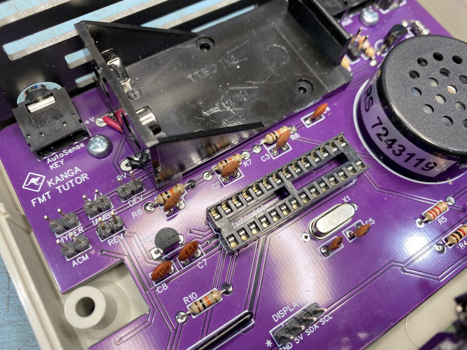
After that we can get into the build, It took me a while to actually fit the socket in the hole, I had a few bent pins due to soemone being heavy handed with it putting it into the anti-static foam, but once straghtened with a pair of pliers it soon fitted snugly into the holes. I had a dodgy pad on the back of mine which hopefully was not in the rest of the production but it would not take solder at all, I had to leave a niced sized ball of solder on the leg, not pretty but hopefully it will do.
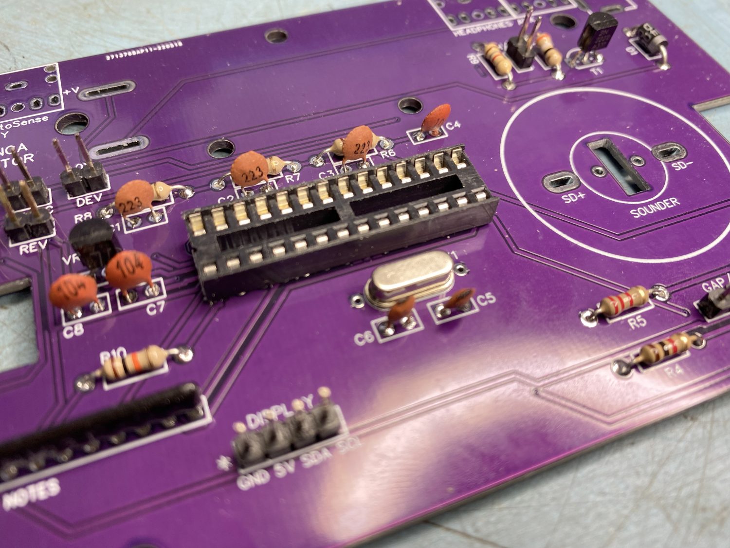
Make sure that the IC Socket is installed the correct way round.
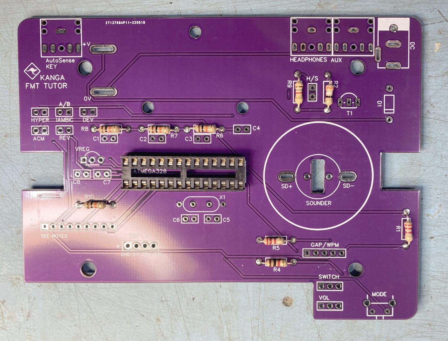
The next job is to install the resistors.
I like that not only have they provided a rather decent colour chart for resistors for those of us that cannot remember the colours, but also next to each value in the ‘Parts List’ there is another hint to which is which value.
Great for new kit builders.
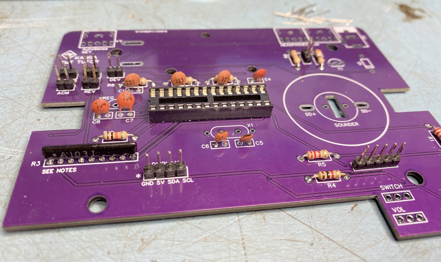
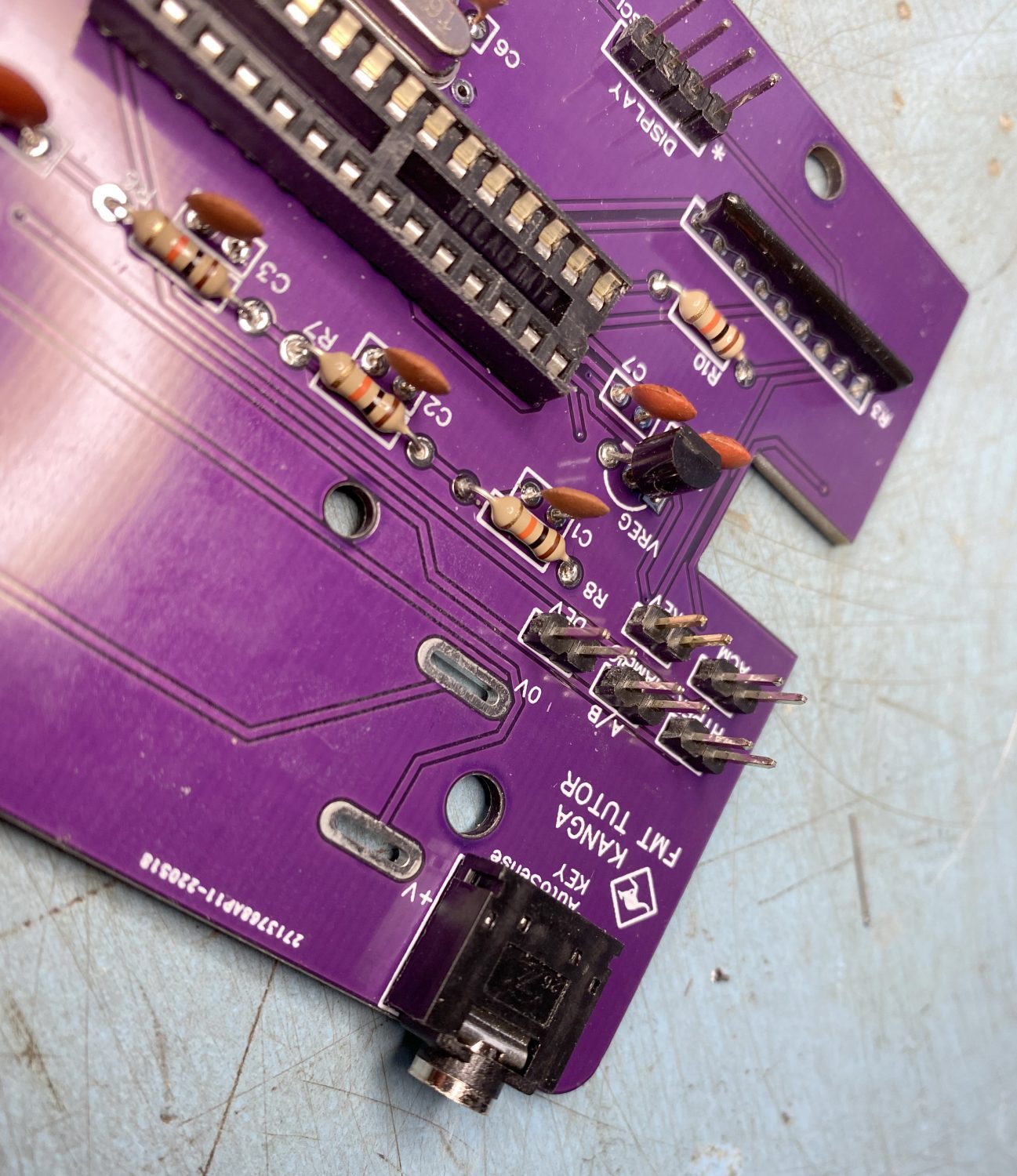
The resistors all installed.
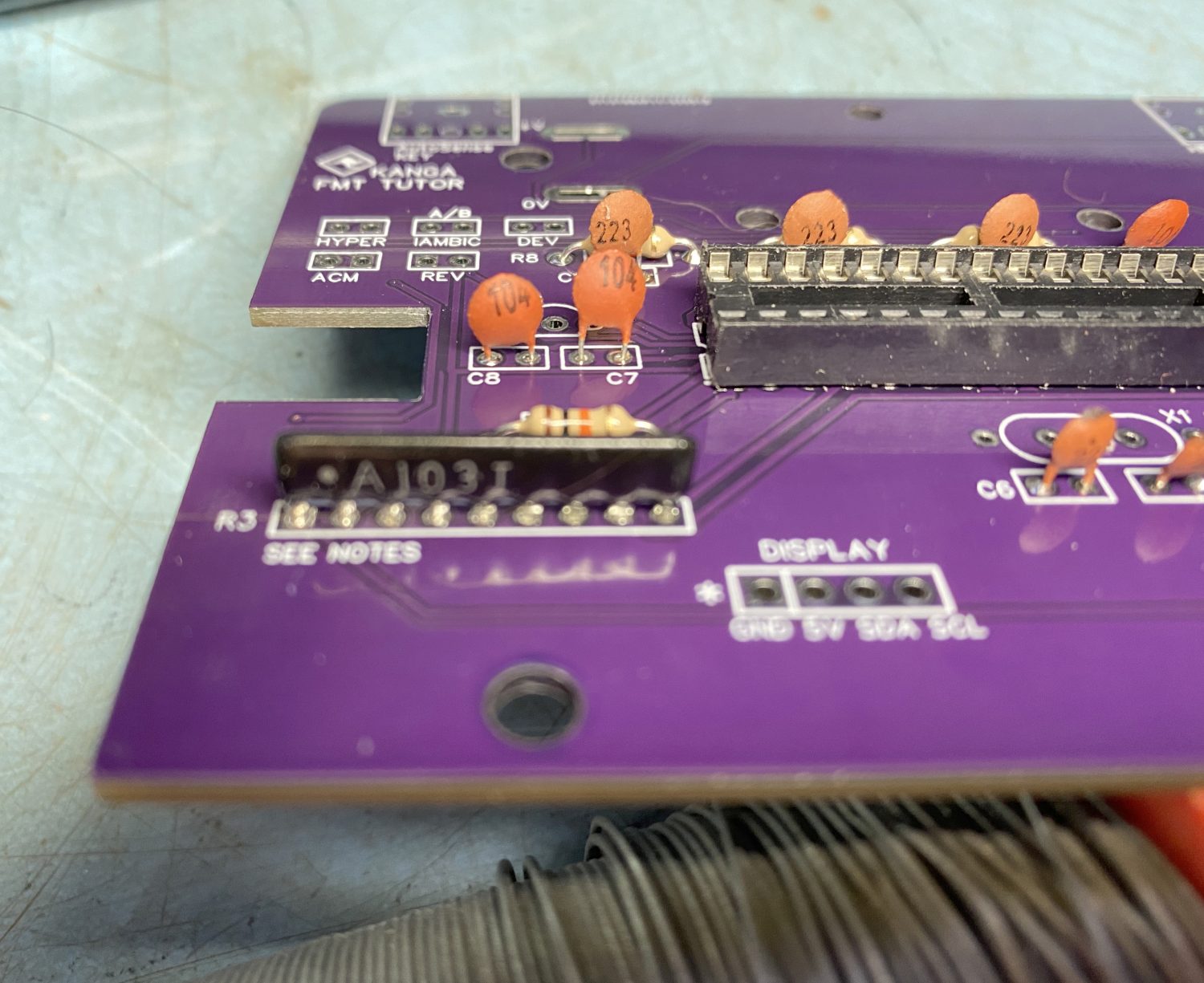
Take care installing the capacitors, they are fairly straightforward, but you still need to make sure of the values.
The Capacitors, all of which are ceramics went in as easy as the resistors, just be careful with the vales, I have a magnifying lamp that comes in handy when the markings are just beyond your eyesight.
This went alright up until C5 and C6 which are labelled wrong in the Instruction guide, a simple over sight.
The resistor pack is next.
Just be careful of the labelling on this item.
There should at least be a visible ‘Dot” to donate which end is pin 1.
Really sorry for the poor quality photos, all taken with my iPhone.
The Jumper pack complete with Jumpers.
The Jumpers are the worst part of this build, trust me it's more fun from now on.
Fitting the pins is somewhat fun.
if you aim to just solder 1 of the pins in place first, then you can see if it needs moving, and then it is relatively easy to set the header pins as near to vertical.
Once you are set you can then solder the rest of the pins in place.
Small Jumper sets, such as the 2 Pin Jumpers used here are a pet hatred of mine, you always end up warming up the odd finger or two when doing these, but you do get used to it after a while, either that or your skin toughens up!
Again I found a couple of the solder pads just would not take any solder at all, so a quick clean with some very fine 1200 grit emery paper and then try again, this sorted out the problem, I actually used a proper tool for the job called a ‘Pad Cleaner’, looks a bit like a screwdriver with a flat end with very fine rough end surface.
I think there must be something on the boards that is stopping the solder from wanting to stick, maybe grease from my hands, but at least sorted.
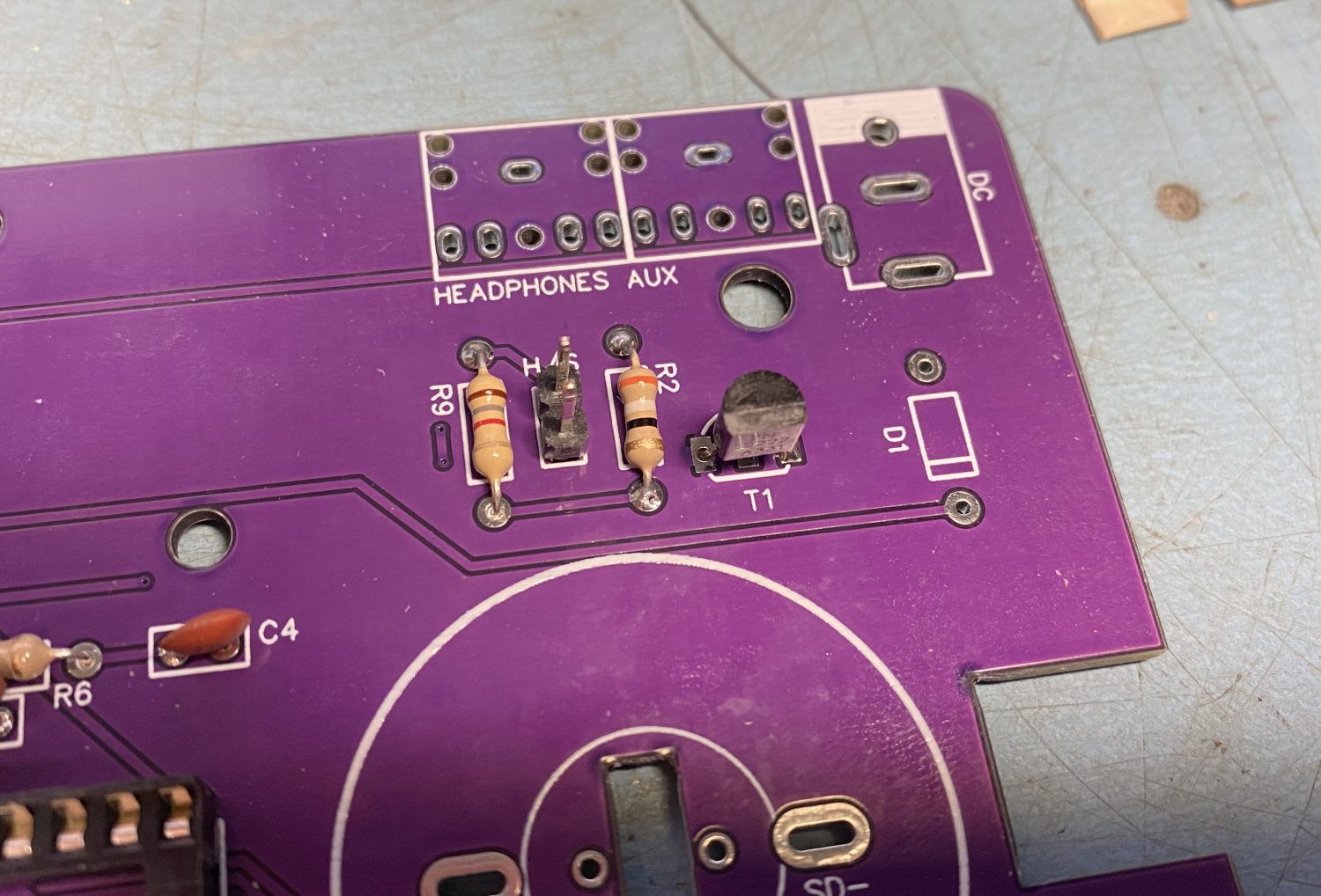
T1 (2N2222) Transistor installed.
The Voltage Regulator (78L05) Installed.
The 2 transistors are next, and very nicely labelled on the PCB as T1 (2N222) and VREG (78L05), there is no real way that you can get this wrong, bUt care should still be taken not to accidently swap these two round.
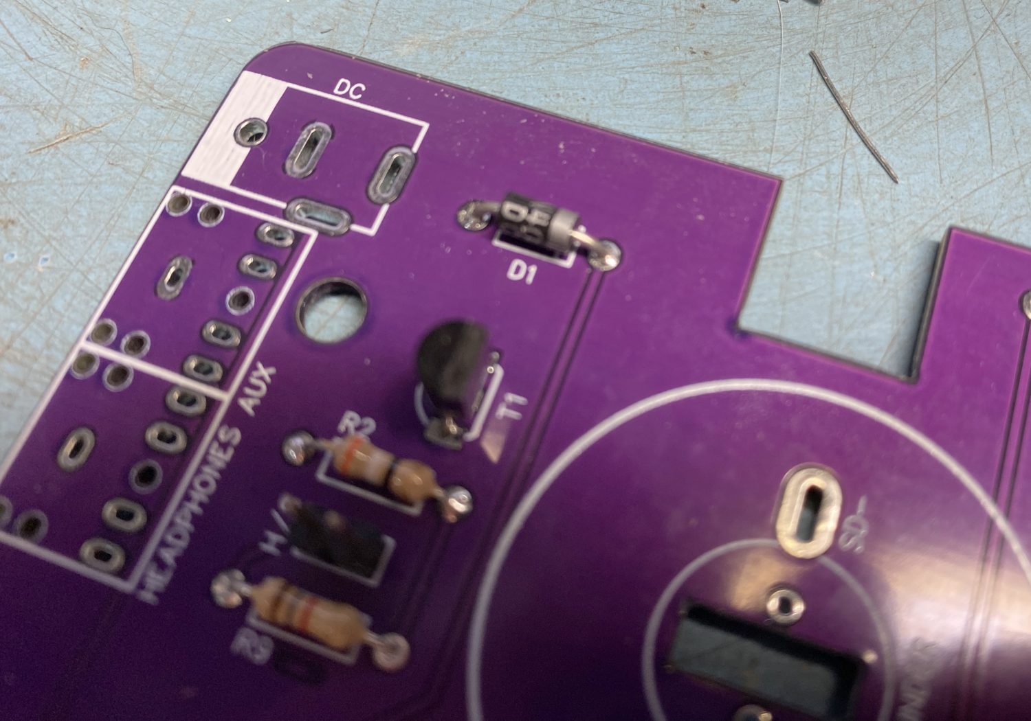
Diodes need to be put in a certain way round, thankfully the ones supplied here are easy to see which way that they need to be inserted into the PCB
Make sure that the Diode is installed the correct way round.
The 16 MHz Crystal is next, it is nice to see that the designer has made it very easy to ground out the Crystal which is a very normal thing to do.
The 16 MHz Crystal can be installed either way round.
There is a slight modyfication to be made to the ‘Power’ switch which involves cutting off a small tag on the switch itself, nothing too crucial but still needed to be done.
In fact you will need to do this to all three of these potentiometers.
The Mode switch can always be a little tricky to get flat, best way to do these is to solder in just 1 pin again on the ground side of the switch, i.e. the outer pins on each side of the ‘Mode’ switch, then as we did with the Jumper pins, you can have a quick look and reheat the solder just enough to send the switch home.
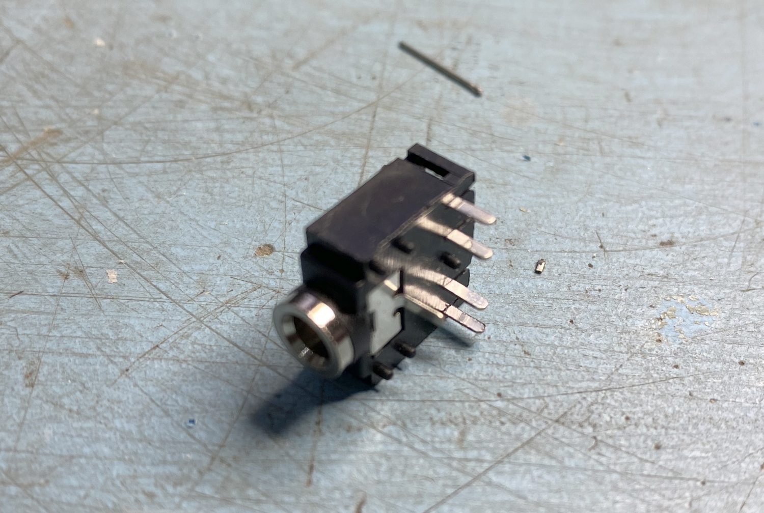
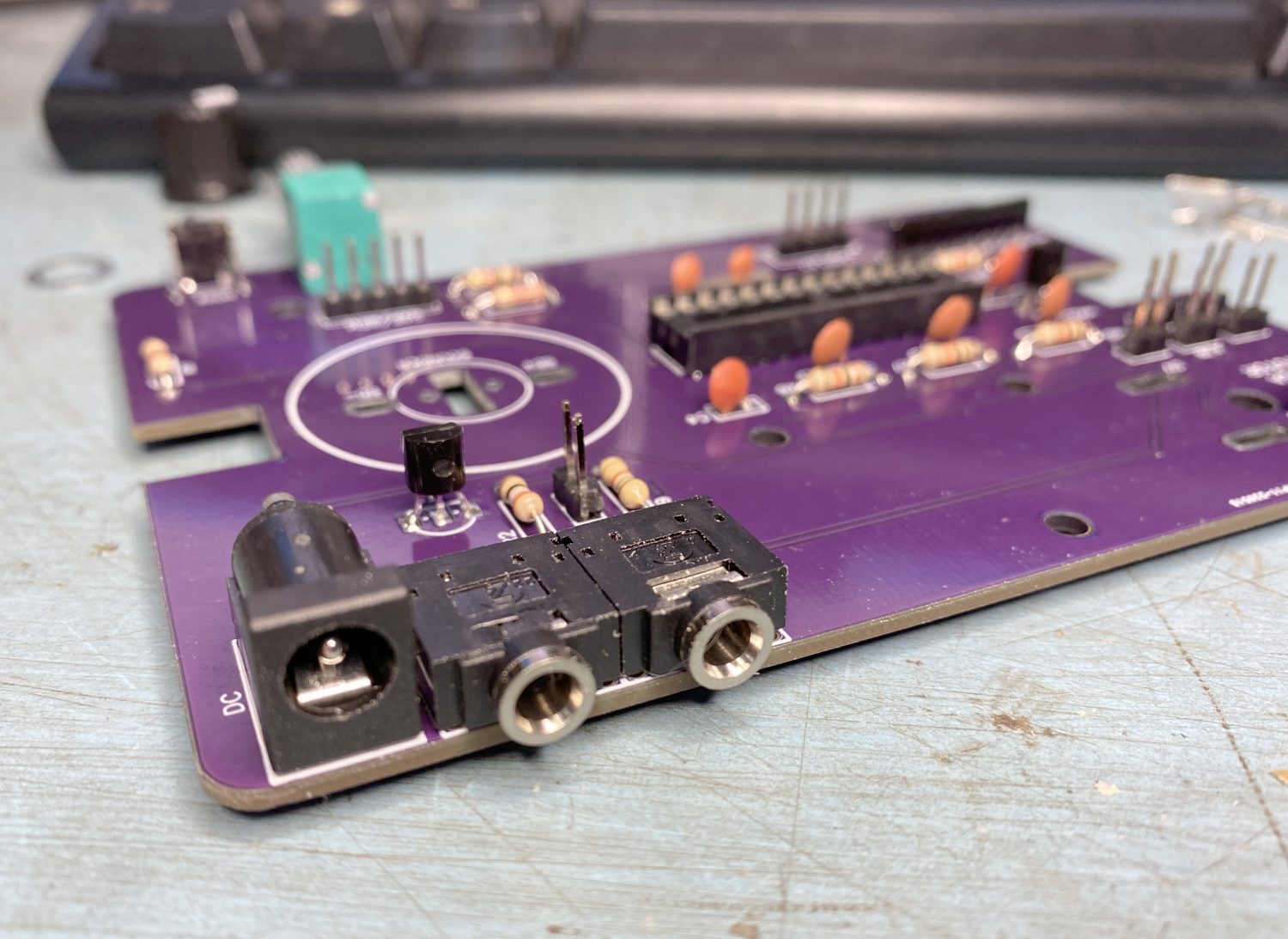
The pins on these 3.5mm Jack Sockets become easily bent over, check them before fitting.
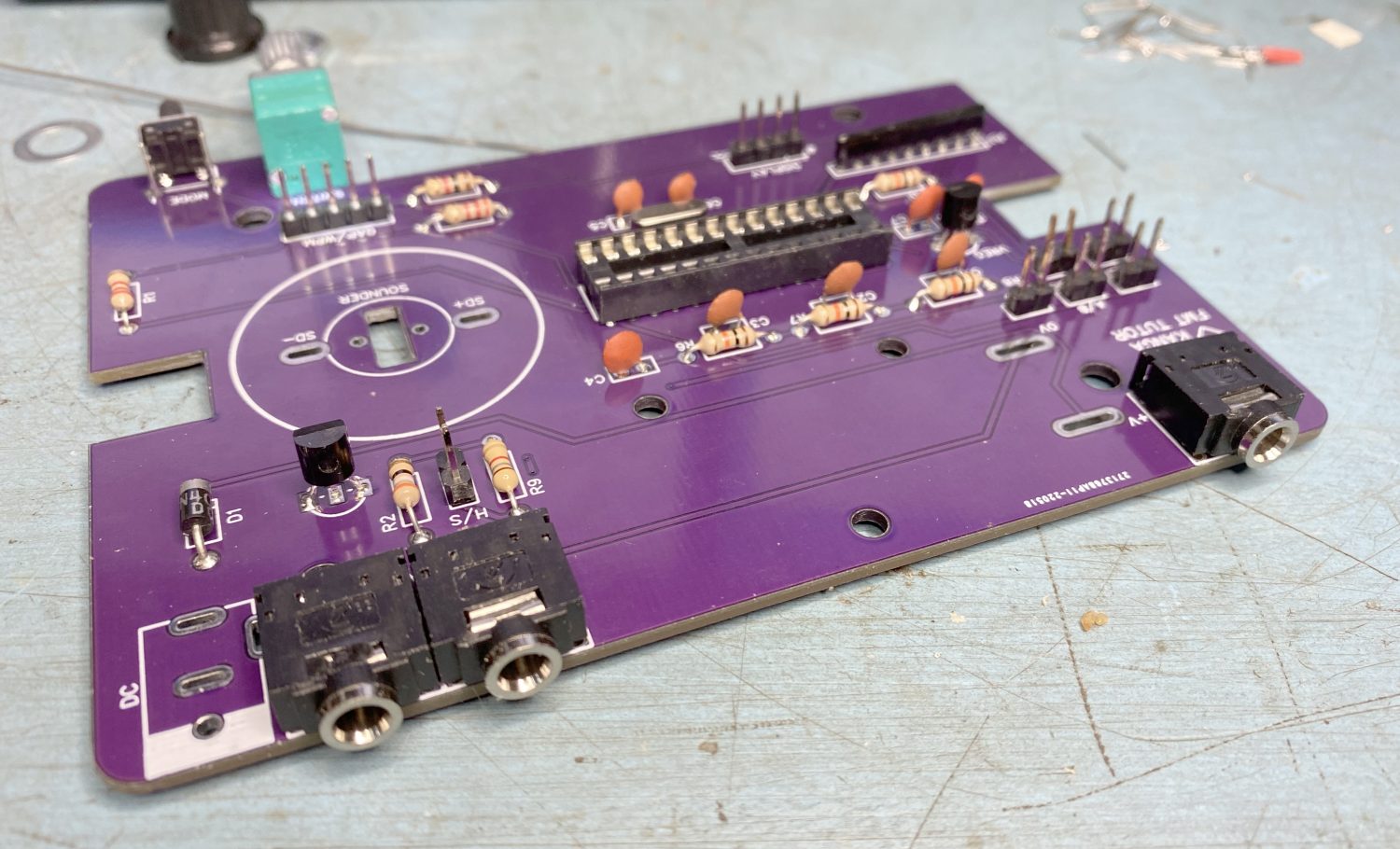
All the sockets installed and pushed down flat against the PCB.
The 3 x 3.5mm Jack sockets are fitted next, these are quite a snug fit so you should not have any issues installing these, except to just check the legs, the pins are made of very thin metal and easily bent over, most of mine were far from straight, but easily remedied.
The Power Connection is next and again is very straight forward.
Just make sure that all these connections are flat and snugly fitted.
The Installed DC socket next to the two jack sockets for the 'AUX Out' and 'Phones' connections
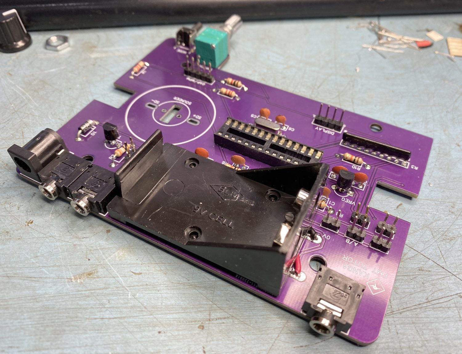
When fitting the battery box you are asked to cut the wires down to about 20mm in length, there is no need to be over precise here as any excess can be hidden between the box and the PCB.
The large area with the slotted sockets are for where the Battery Box is to be installed.
When you get to the point where you need to screw the holder down.
Just be a little careful here – the screws are small.
They do not need much to hold the battery box in place, and can easily be threaded,
The battery Holder fitted in place ready for screwing down.
Now we get a little brake from the main board and we do something a little fiddlier – The Small Header board that mounts the two pots for the ‘Gap’ and the ‘WPM’.
A third hand will be really useful here, which is why I must have forgotten to take a photo of this bit – Opps!
At this point it is a good idea to reach for those horrible ‘Handy Helpers’ hat you put on the shelf somewhere as you thought that you would never use them, this is one of those occasions where they actually are useful.
Either that or a small vice.
I noticed when I did mine that mine actually pointed in towards each other, so I redid them making sure that not only were they flat to the PCB but also pointing in the same direction as well as you can move them a degree or two off centre.
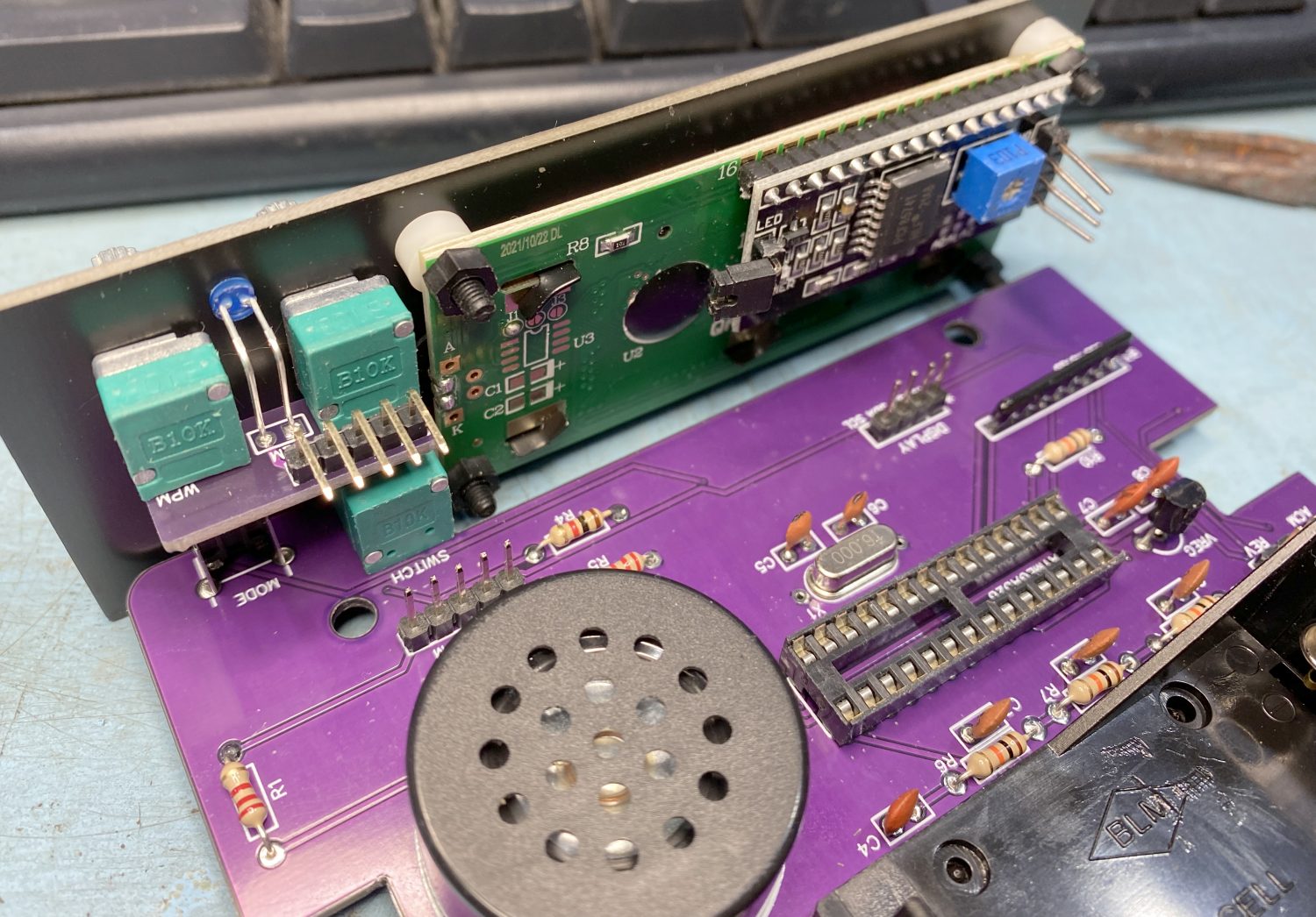
Now on to the front panel.
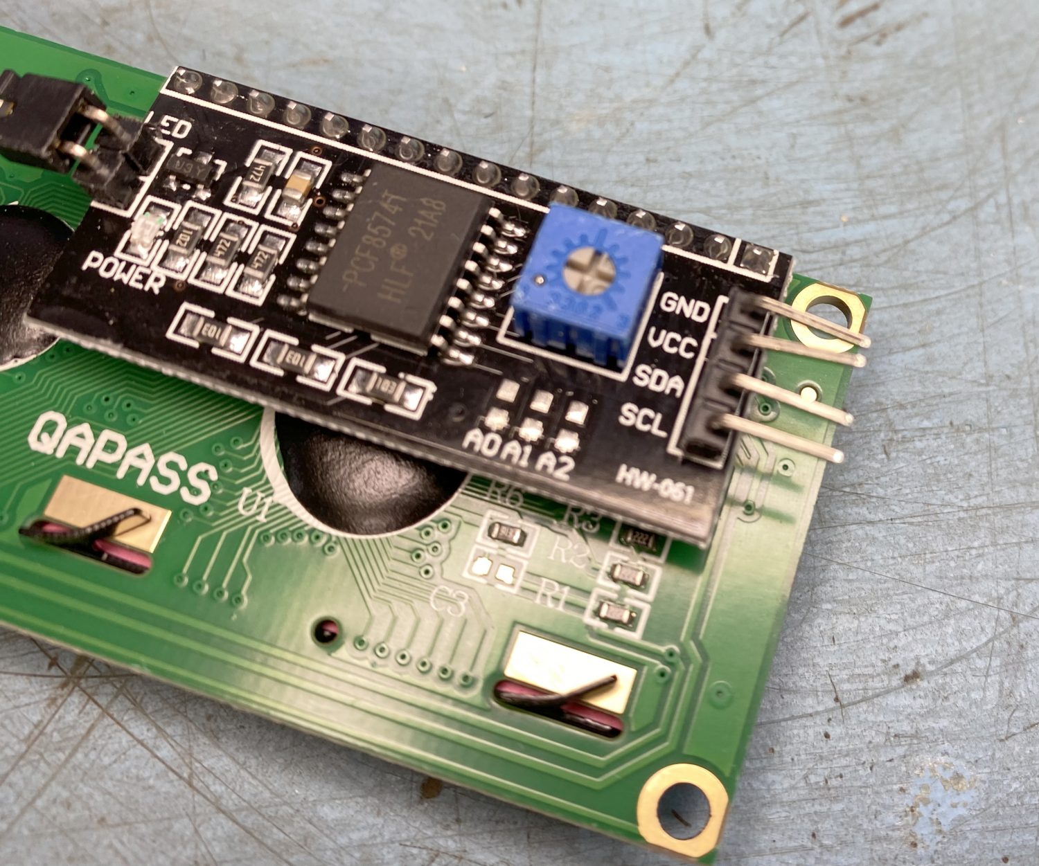
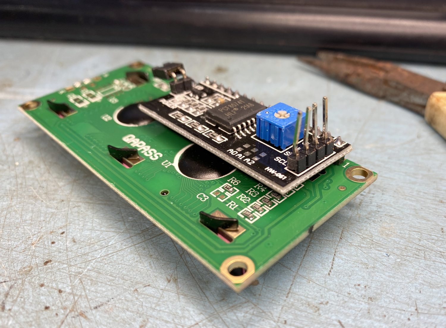
We start by having to sort out a slight design change, in that the pins on the back of the LCD Display need to be straightened, this can be gently done with some small pliers.
Once that had been done the installation of the LCD panels is straight forward, makig sure that the white spacers are used and also that the screws only need to be just nipped down, the screws are plastic and will not take you being heavy handed at this point.
Remember this 'Pot' later you will need to adjust this to get the display to work properly.
When you fit the board that will be the ‘Gap’ and ‘WPM’ controls, just fit these hand tight until you are happy with the LED placement.
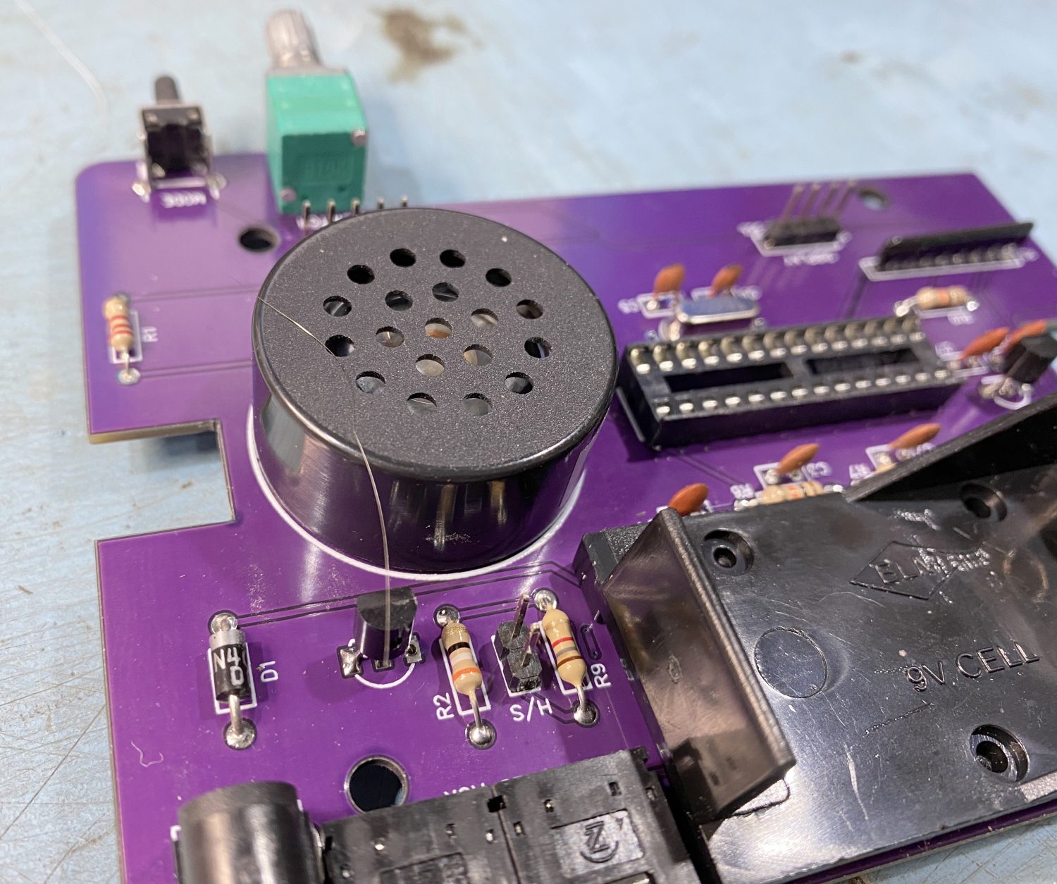
The LED needs to be bent over and stuck through the hole, so kind of gauge where it needs to be bent and then stick it in the hole on the front and also through the PCB.
Make sure that the LED is installed the right way round. the longer of the two leads needs to go through the round hole on the PCB, the other one is defiantly square.
The straightened pins on the back of the LCD Display unit.
The Blue LED needs to be roughly fitted to make sure that it is set at the right depth.
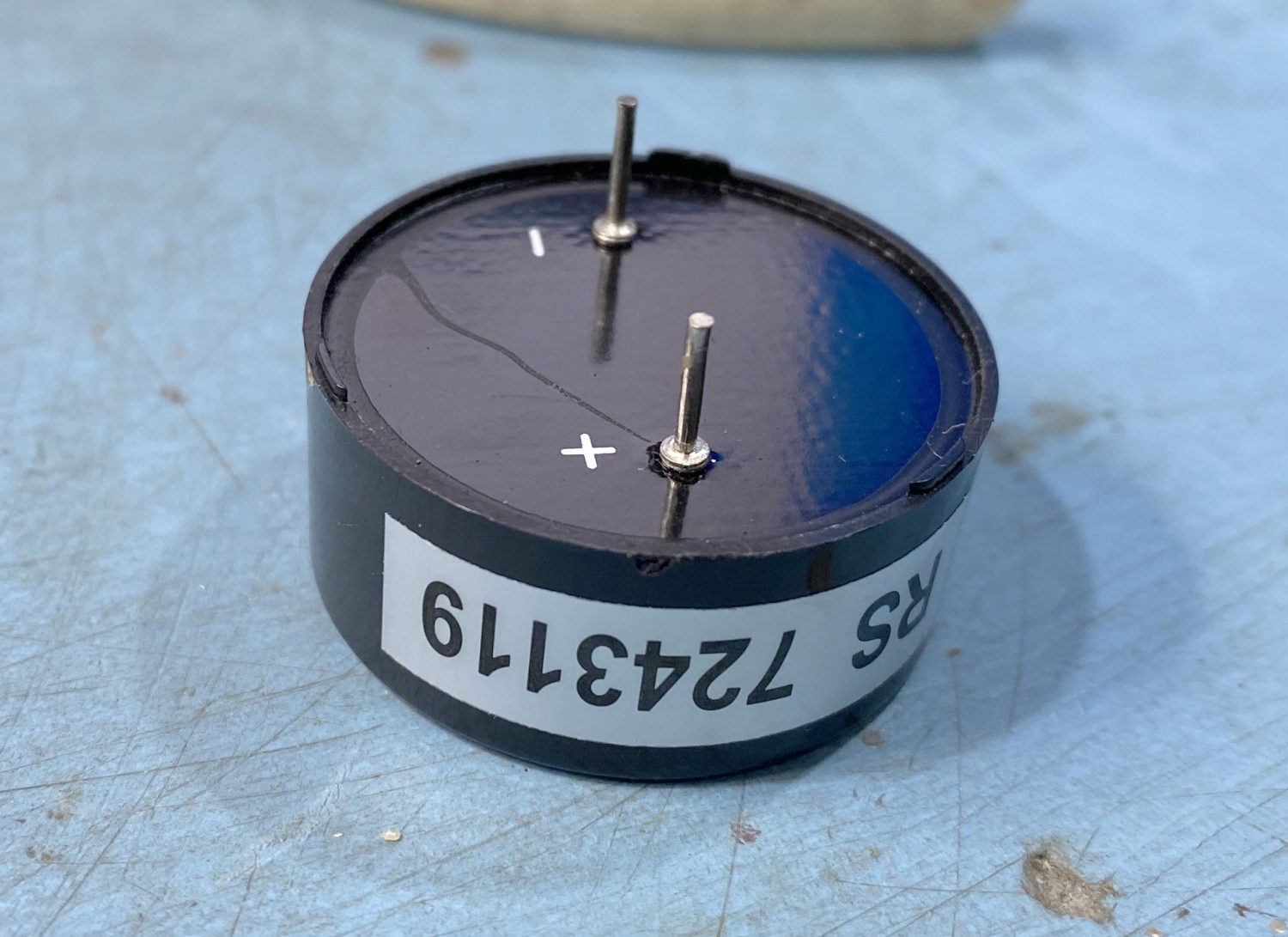
The 'Sounder Unit' needs to be installed the correct way round.
The 'Sounder Unit' installed.
Install the Sounder Module at this point.
It does have a positive and a negative terminal so please make sure that it is fitted correctly, the markings on the PCB are very good.
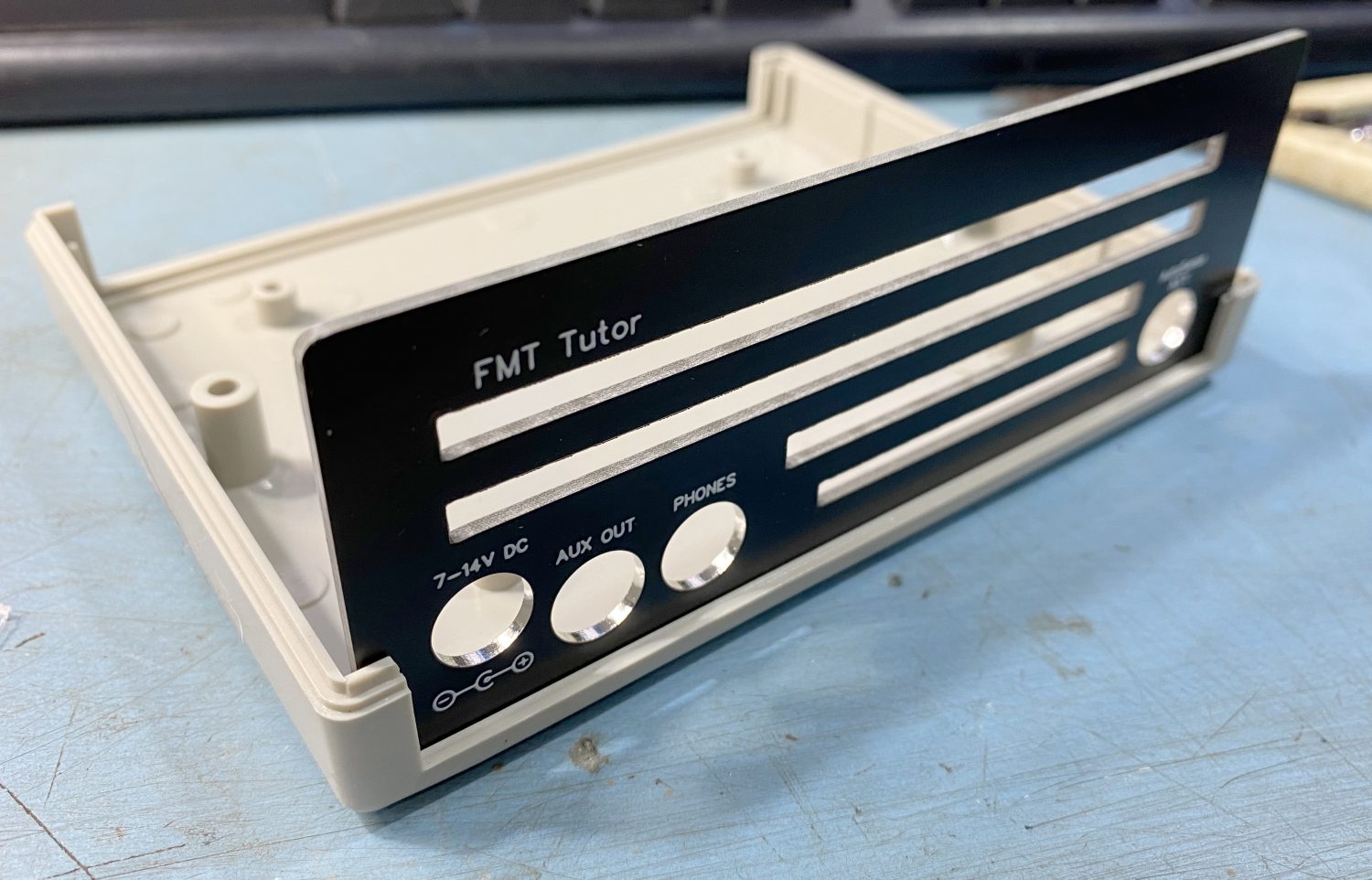
Now for the fun part, well only if you have not enjoyed yourself so far, we get to build the unit up.
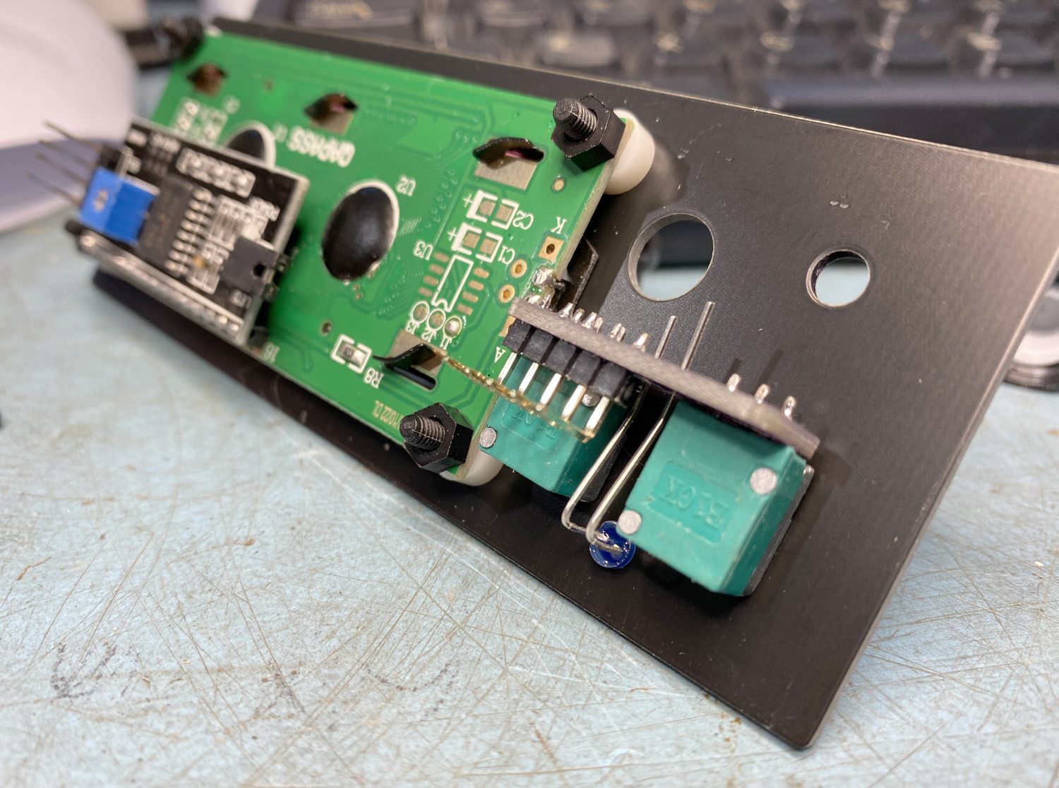
Fit the back panel into the bottom of the cabinet, you will need to remove the blanking plates as these will not be used, and once done you can slot the back panel into place.
The rear panel slotted into the bottom part of the cabinet.
Loosely fit the front to the main PCB and then slot the front panel into the available slots in the base of the cabinet and gently lower into place.
Fit the front panel to the PCB as such, it does not need to look pretty at this stage.
Slide the front along with the PCB into place, and it will all slide together nicely.
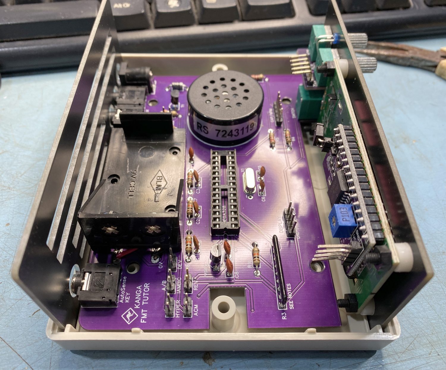
There really is not much more to be done.
A quick shuffle of the base will make sure that all of the parts are down and in their correct position ready for screwing down.
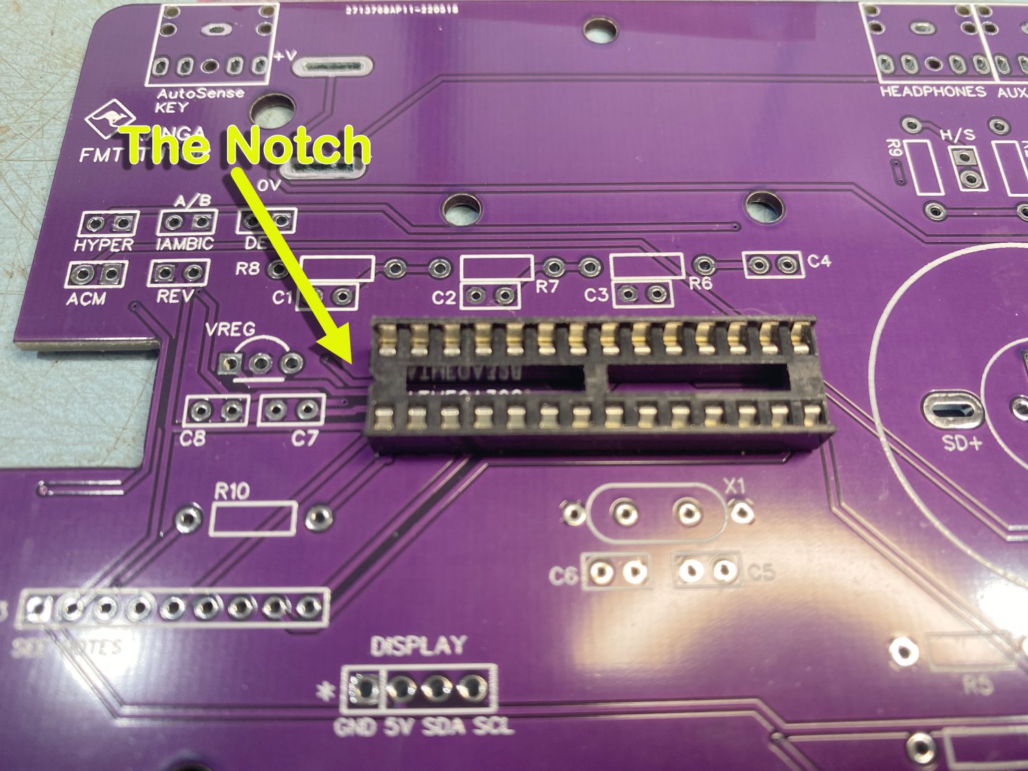
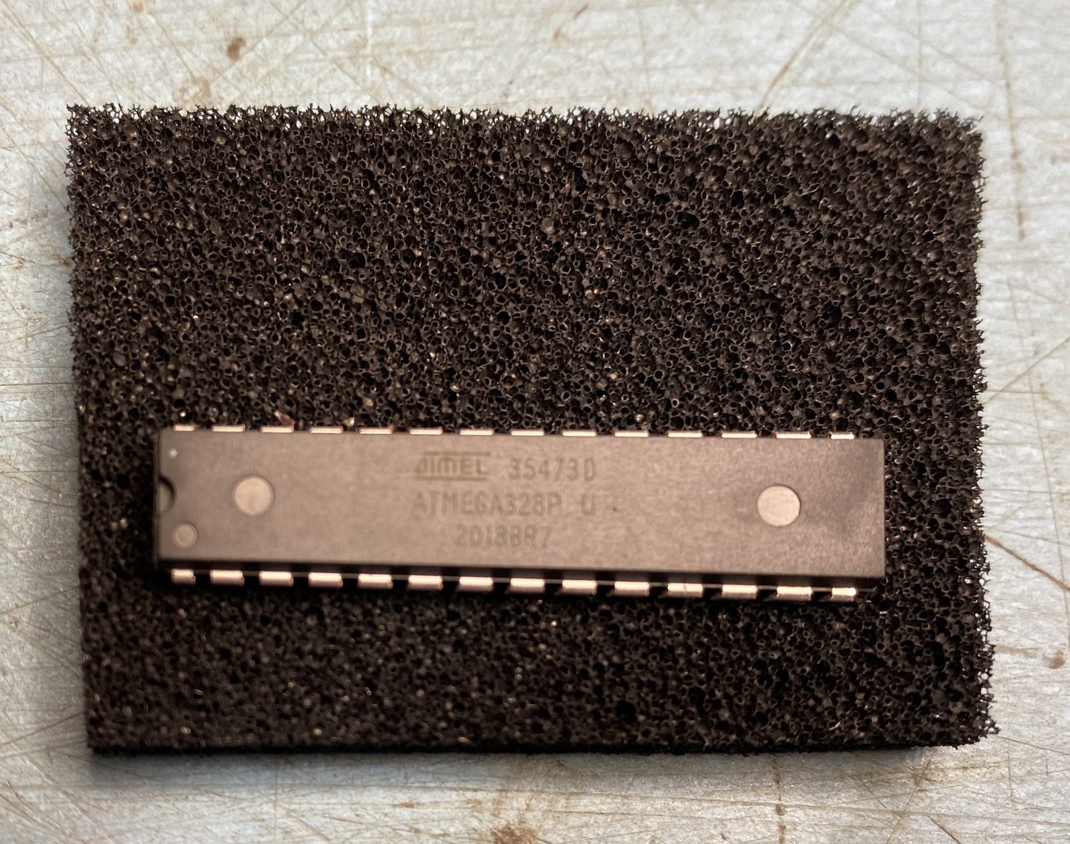
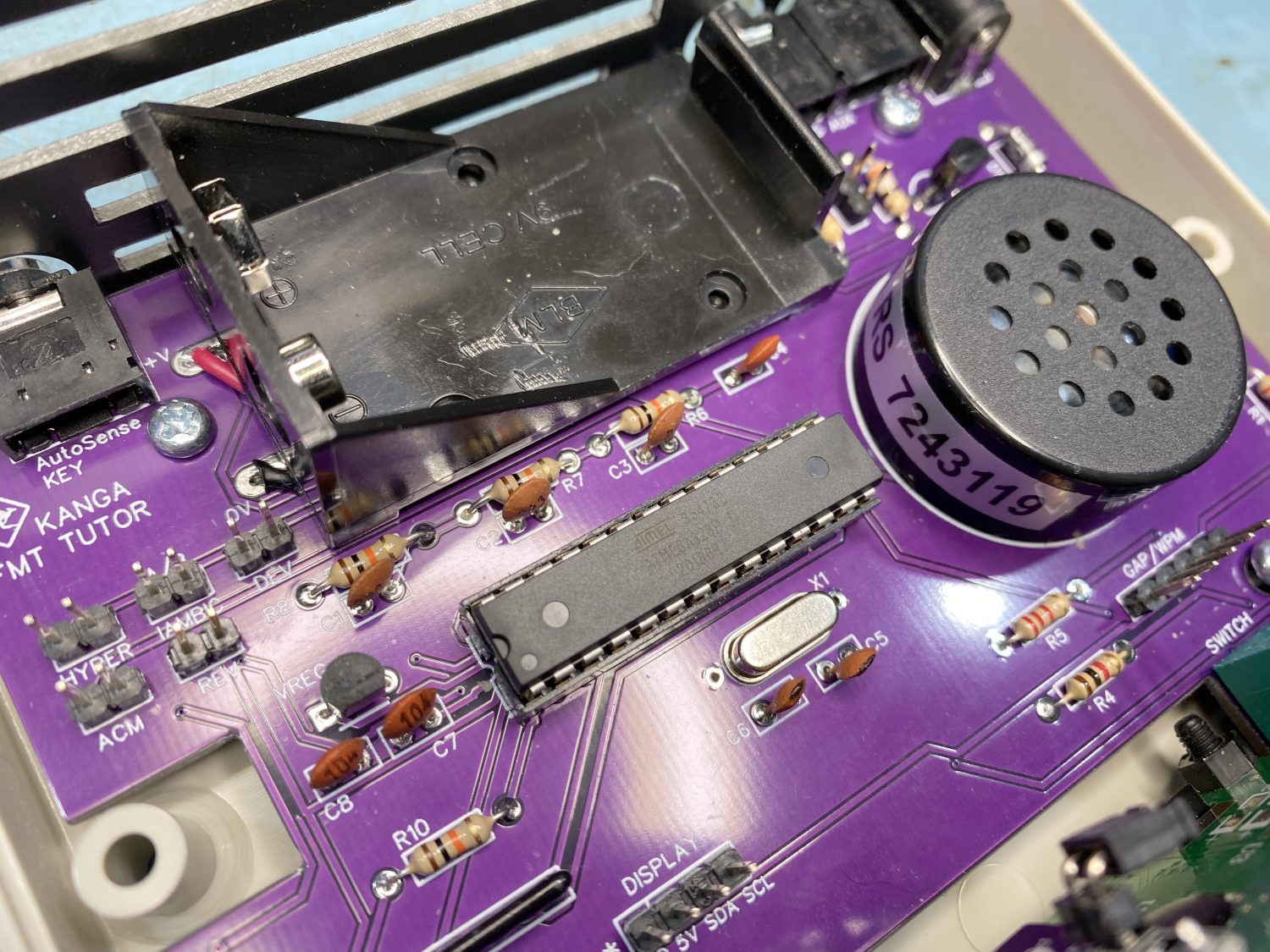
Once this has been done you need to look at the PCB and get accustomed with where pin 1 of the IC socket is as we now need to install the processor IC.
The ATMEGA Processor IC all configured ready for installation.
Make sure that you make a mental note of which end the notch is at to be ready to install the Processor.
This is a sensitive device and it can be easy damaged by incorrect handling. – Do NOT touch the pins, and when installing it into the socket, ‘Take your time’ and be careful ‘NOT to bend any pins’.
We are nearly finished and soon you can relax with a beer – I wish!
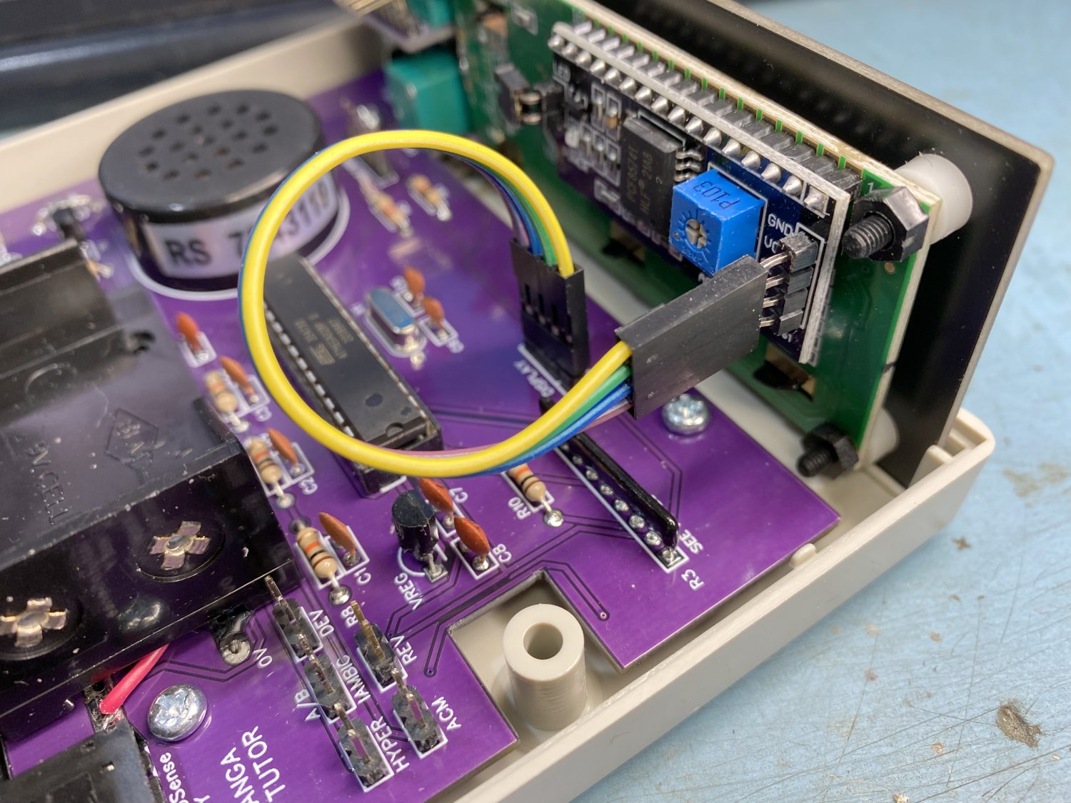
The First of the jumper cables is the 4-way cable.
The connection that you had to straighten out the pins on my need a little bit of care with, as the pins may not be true, so take your time when installing this and also make sure thatyou have not twisted the cable round on one end by 180 degrees, the image in the manual on on here is correct.
Install the 4 way cable like this, make sure that you do not twist it a further 180 degrees by mistake.
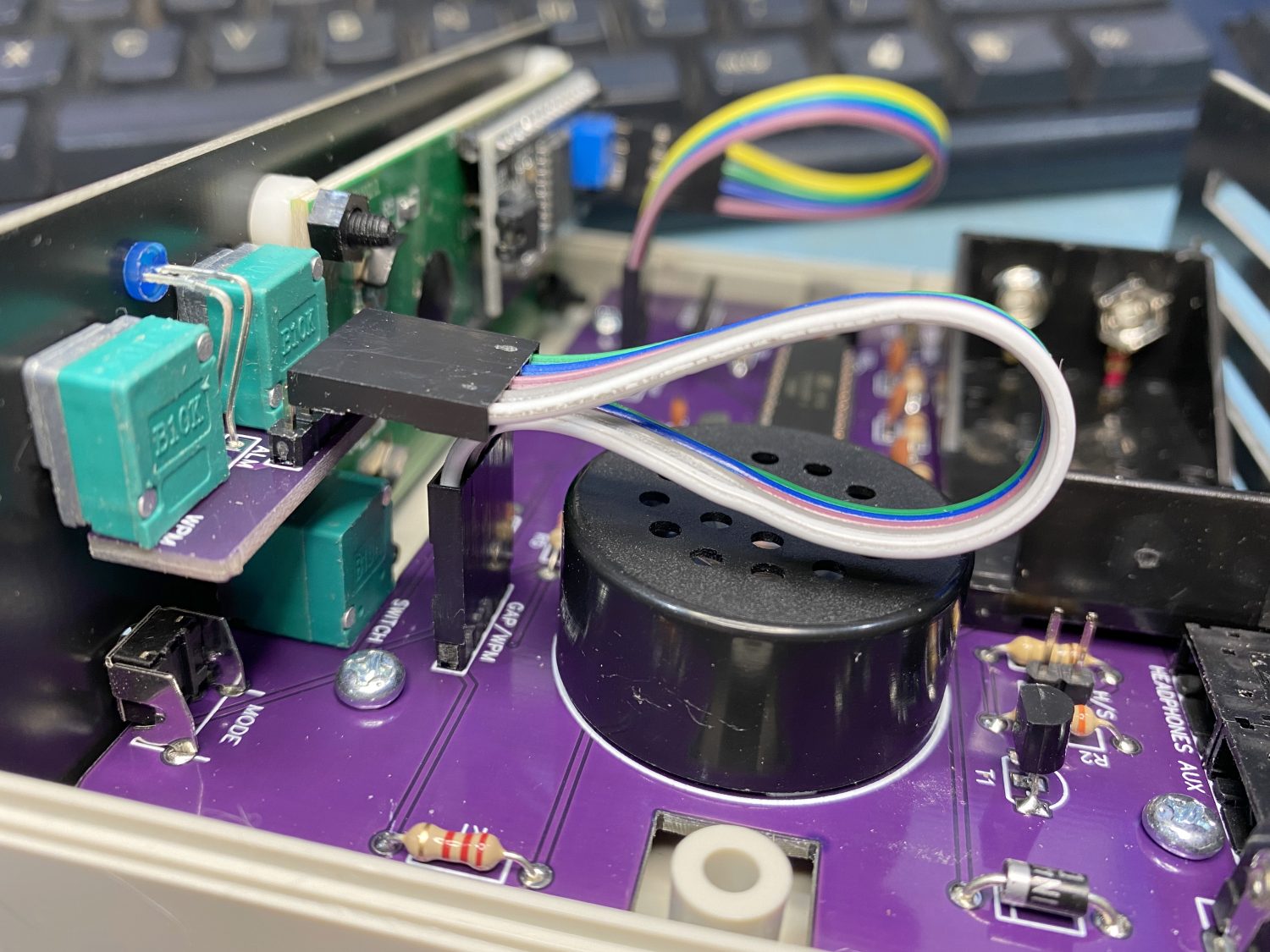
And the 5 pin link cable can also be installed as the photo shows here.
Install the 5 way cable as shown here.
At this point you can fit the 9v Battery (If you have one which I did not).
Also fit the ‘Jumpers’ at this point, I may have missed this in the manual but decided to do it here anyway.
Set them up like this for starters as these settings will suite most people looking to learn CW.
HYPER Jumper : OFF ACM Jumper : ON H/S Jumper : OFF IAMBIC Jumper : ON REV Jumper : OFF DEV Jumper : ON
Where I have stated ‘OFF’, just install a jumper onto one leg, this way you will not have to hunt for a jumper at a later time.
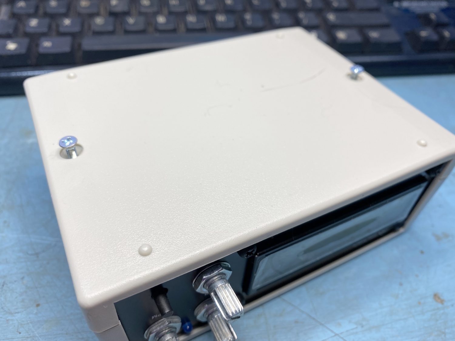
Now you get to screw the cabinet together.
All way through this build I have been pleasently supprised with the Build quality of this kit, and smalll things such as having proper screws/bolts holding the top and bottom cases together instead of what some kit manufacturers do which is use cheap ‘Self Tapping’ screws that normally do not work after changing the battery a few times.
Finally screw the case together, it is really nice to see proper bolts and not self tapping screws.
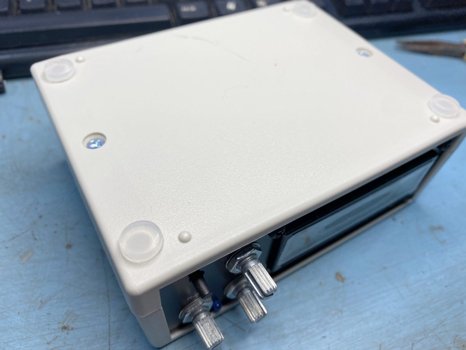
Just add the feet to the bottom to make sure that your other equipment does not get scratched up and you are done!
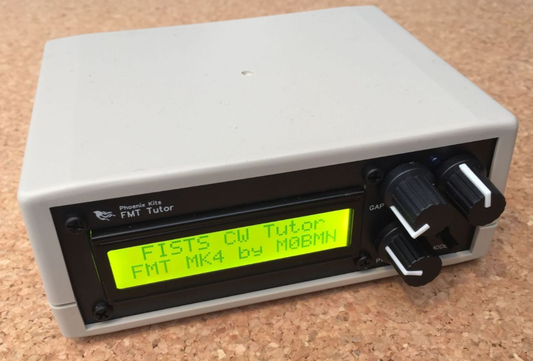
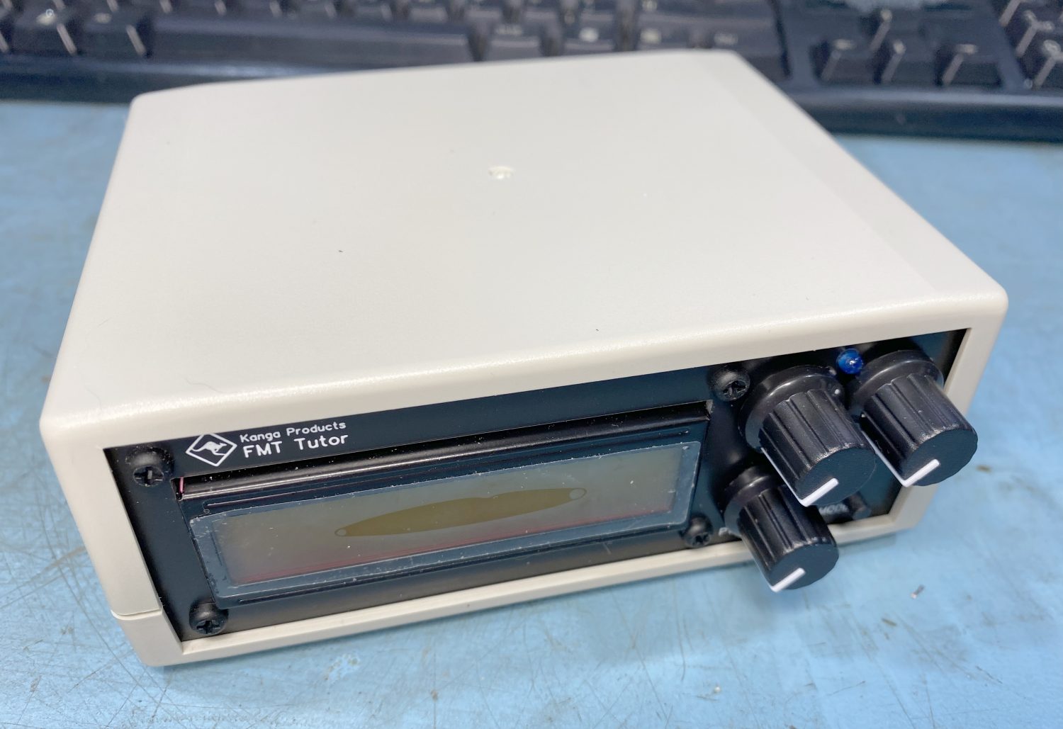
The finished Kit, just need to find an bloody battery!!!!
Just a final mention.
If you switch the unit on and all you see is a load of shaded squares, do not worry, this is normal, you just need to adjust the pot on the back of the display.
I did not need to install the other small pot that comes on a seperate small board with the word ‘BRIGHTNESS’ etched upon it, all this did was turn up the brightness on the LCD, which even on its default setting I found to be bright enough. Turning this up to say full will shorten the life of the LCD display unit so please keep this in mind.
Final Thoughts
The only bad thing for me was the poor quality prints that I got, but then I am also comparing this to previous kits, all of which had nice printouts supplied that did not have the feel that this was a rush job.
But this does not take anything away from the kit.
As far as kits go, it is certainly a great kit for first time Electronic Kit Builders, or a Chemo and Radiotherapy brain addled subject with the concentration of a dead toad.
It took me three days to build this but as stated I have a few issues at present, it time alone it took me a steady 3 hours of when I was concentrating, it was certainly fun and hassle free.
Would I recommend this to anyone? – EVERYONE….
Because I did not read the manual as well as most, I had to e-mail Paul regarding the jumper settings, support from Paul was great, kind, understanding and very fast, again this shows he cares a lot about his products.
I would have liked to see a battery included with the kit, and then the cost of the battery added to the cost of the kit, bu batteries have a shelf life and then you have the waste costs of dead stock to think about, so it is kind of understood.
I hate 9v batteries and never seem to have spares, the shop is a good way off and requires planning when you are disabled and cannot drive yourself, so it is always a bind when this happens.
I know that it can be plugged in, but I would have preferred to see AA Batteries used instead, only because they are cheaper and more often than not there are spares easy to hand in most houses, even if it does mean steeling them out of the Sky remote.
The good old 9V battery is getting expensive nowadays and you never seem to find the ones that you put away for a rainy day, buying a new one from Tesco’s is a pain.
It is a small thing but having a case that screws together with proper screws and not horrible self tapping screws is very nice touch and again shows that this is produced for quality and not cheapness, even though it is a very cheap kit.
Great Kit, Easy to Build, Works as Described, and Fun to make… 10 out of 10.
Kanga Products Website
Check out their website, they have quite a few very useful kits worth checking out.
I am now retired and living on the Isle of Man, my background is as varied as it gets, ranging from Information Technology to Graphic Designer and 3D VFX Artist, using and teaching Autodesk Maya, Softimage, and Smoke, one of more enjoyable positions. Since Moving to the Isle of Man I try to keep myself to myself and work on the house, I don't do much with regards to Amateur Radio or Electronics anymore, but I am still interested in the hobby and may well get back into it one day....